Section 5: Printer Configuration
LCD DISPLAY |
| DEFINITION | |
|
|
| |
CARD FORMAT |
| Before a PCMCIA card can be used, it must be formatted. | |
YES | NO | Note: Formatting a card destroys all data currently stored on the card. | |
|
| ||
|
| 1. | Use the CURSOR keys to step the cursor to desired option. If Yes is |
|
|
| selected, the printer will enter the Card Format mode. If No is selected, the |
|
|
| display will advance to the mode display. |
|
| 2. | Press the ENTER key to select the option and advance to the next display. |
|
| ||
MEMORY FORMAT | Before the internal Expanded Memory can be used, it must be formatted. | ||
YES | NO | Note: Formatting the Memory will destroy any stored data. | |
|
| ||
|
| 1. | Use the CURSOR keys to step the cursor to desired option. If Yes is |
|
|
| selected, the printer will enter the Memory Format mode. If No is selected, |
|
|
| the display will advance to the mode display. |
|
| 2. | Press the ENTER key to select the option and advance to the next display. |
|
|
| |
CARD MODE |
| To exit the Card Mode, power the printer off and then back on. | |
|
|
|
|
SERVICE MODE
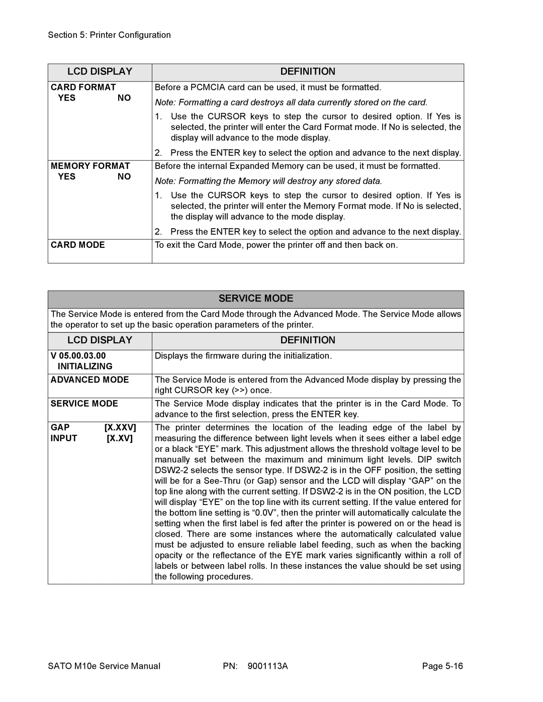
The Service Mode is entered from the Card Mode through the Advanced Mode. The Service Mode allows the operator to set up the basic operation parameters of the printer.
LCD DISPLAY | DEFINITION | |
|
| |
V 05.00.03.00 | Displays the firmware during the initialization. | |
INITIALIZING |
| |
ADVANCED MODE | The Service Mode is entered from the Advanced Mode display by pressing the | |
|
| right CURSOR key (>>) once. |
SERVICE MODE | The Service Mode display indicates that the printer is in the Card Mode. To | |
|
| advance to the first selection, press the ENTER key. |
GAP | [X.XXV] | The printer determines the location of the leading edge of the label by |
INPUT | [X.XV] | measuring the difference between light levels when it sees either a label edge |
|
| or a black “EYE” mark. This adjustment allows the threshold voltage level to be |
|
| manually set between the maximum and minimum light levels. DIP switch |
|
| |
|
| will be for a |
|
| top line along with the current setting. If |
|
| will display “EYE” on the top line with its current setting. If the value entered for |
|
| the bottom line setting is “0.0V”, then the printer will automatically calculate the |
|
| setting when the first label is fed after the printer is powered on or the head is |
|
| closed. There are some instances where the automatically calculated value |
|
| must be adjusted to ensure reliable label feeding, such as when the backing |
|
| opacity or the reflectance of the EYE mark varies significantly within a roll of |
|
| labels or between label rolls. In these instances the value should be set using |
|
| the following procedures. |
SATO M10e Service Manual | PN: 9001113A | Page |
