Issue 10 June
Copyright 2005, Avaya Inc All Rights Reserved
SOC
Installation and Repairs
About This Book
Contents
Contents
Contents
Contents
Completing Installation and Cable Pinouts 151
Contents
Contents
Adding or Removing Hardware 231
Contents
Contents
Installing a J58890CG Power
Contents
Appendix B Access Security Gateway 361
Page
Conventions used in this book
General
Typographic
Admonishments
On the Web
How to get this book
Physical dimensions
Trademarks
Non-Web
Where to get additional help
Avaya support Support Number
Tell us what you think
Security Issues
Remove/Install circuit packs
Antistatic Protection
License File
Pre-installation checklist
Pre-installation checklist
Read This First
Installing and Cabling the Cabinets
No direct connection
Go to the RFA website
Selection
If you have problems with RFA
Correcting Shipping Errors
Check Customer’s Order
Unpack and Inspect
Equipment Packed with the Compact Modular Cabinet
Comcodes for CMC1 Description
Comcodes for CMC1
Comcodes for CMC1 Description
Comcodes for CMC1 Description
Set the Carrier Address ID All Cabinets
Install the System Cabinets
Floor-Mount the Cabinet
Typical Floor Mount Installation
Or 3 Vertically Mounted Cabinets
Install Plywood Backing onto Wall
Single-Cabinet Installation
Wall-Mount the Cabinets
Left Panel Used as Mounting Template
Install Cabinet a Wall-Mount
Typical Wall-Mount Installation
Typical Vertical Multicabinet Installation
Install 2 or 3 Vertically Mounted Cabinets
Typical 3-Cabinet Installation
Install 2 Cabinets Vertically and 1 Cabinet Horizontally
Left and Right Panel Installation
Install Left and Right Panels Wall-Mount
Check AC Power
AC Power and Ground
Approved Floor Grounds
Approved Grounds
Uninterruptible Power Supply
CMC Power Supply
CMC Power Switch
Connect Cabinet Grounds and Other Grounds
Install the Ground Block
Typical Cabinet Grounding
Connect and Route Cabinet AC Power Cords
Install Coupled Bonding Conductor
Routing AC Power Cords to a Power Distribution Unit
System Cable Connections
Cable the System
Vertically Mounted System
Cable the Multi-Cabinet System Wall-Mount
Vertically and Horizontally Mounted System
Install Main Distribution Frame MDF and External Modem
Install the MDF
Bottom-mounted MDF with Modem
Typical Bottom-Mount MDF and Modem Cable Routing
Typical Top-Mount MDF Cable Routing
Top-Mounted MDF
Preliminary Dual-Mount MDF Cable Routing
Dual MDFs
Typical Dual-Mount MDF Cable Routing
Install Equipment Room Hardware
Install the External Modem
Cross-Connect the Cabinets to the MDF
Circuit Pack Slot Loading
Circuit Pack Installation
Control Carrier Slot Layout
Definity Audix
Installing and Cabling the Cabinets
Example MDF Connections
Off-Premises Circuit Protection
Install Sneak Fuse Panels
Model 507B Sneak Fuse Panel
Sneak Fuse Connector Pinout Pair/Fuse Pin Numbers
Label the Main Distribution Frame
Label Graphic Symbols and Nomenclature
Set Up System Access
Connecting a PC
Starting Terminal Emulation
Remote connection
Direct connection
Figure notes
Connecting through a data module
Data module settings
Adding a data module
Type add data-module number or add data-module next
Testing hardware connections
Setting the operating mode
Type How to Test and Troubleshoot Data Module
Setting the 7400B+ options
Type How to set the operating mode Data Module
DIP Switch Settings 7400B+ Option
Numeric result codes
Connecting by analog modem
Data Terminal Ready override
Verbal result codes
Smart mode
S. Robotics Modem Dip Switch Settings Description
No echo, offline commands
Load factory defaults
Ringing Option Selection
Set Ringing Option
Single Cabinet Installations
Activate and Administer the System
Power Up System
Deliver or Install the License File
Check Customer Options
System Administration
Log into the System
Check System Status
Set Country Options
System Parameters COUNTRY-OPTIONS
Tone Detection Parameters
USA
Country Codes
LOGIN’S Password Information
Change Craft Password
Password Administration
Login Being Changed
Set Daylight Savings Rules
Type change daylight-savings-rules and press Enter
Daylight Savings Rules
Time
Set Date and Time
English Day of the Week Names Day Name Number
Date and Time
English Month Names Number
Enter change system-parameters maintenance and press Enter
Circuit Pack Administration
Set System Maintenance Parameters
Administer the Attendant Console
Install and Wire Telephones and Trunks
Save Translations
Add Translations
DCP, analog, and ISDN-BRI
302D to Digital Line Circuit Pack Wiring
Analog Tie Trunk Example
Analog Station or 2-Wire Digital Station Example
Digital Tie Trunk Example
Digital Tie Trunk Wiring
Pinout of C6F Cable Wire Color Lead Designation Pin Number
DS1 Tie Trunk Example
Collocated DS1 Tie Trunks
Pair and 4-Pair Modularity
DS1 Tie Trunks Using T1 Channel Service Unit
Hard-Wire Bridging
Install Attendant Console Optional
Dual Wiring of 2-Wire and 4-Wire Endpoints
Install and Wire Telephone Power Supplies
Install 26B1 Selector Console Optional
Administer IP Stations and Trunks
Typical Adjunct Power Connections
Adjunct Power Adapter
Adjunct Power Connections End-to-End
Example Adjunct Power Connections
Auxiliary Power for an Attendant Console
Local and Phantom Power
1145B2 Power Supply
Important Warning for 1145B2 Power Supply
Mounting the 1145B2/1146B2 Power Supply
1145B2/1146B2 Mounting Arrangement
Expanded Power Distribution Unit
Mount the 1146B2 Power Distribution Unit
Install the Wall-Mounting Plates
Install the Battery Mounting/Wiring
Install the Expanded Power Distribution Unit
Back-Up Battery Rating
Power Supply LEDs LED Color Meaning
Power Up and Test the Power Supply
Wire the 1146B2 Power Distribution Unit
Typical Wiring to a Telephone
1152A1 PDU UL 1950 Compliance Complies
1152A1 Mid-Span Power Distribution Unit
Reset LEDs on Power Distribution Unit
Important Safety Instructions
Using the 1152A1 PDU
Connect the Cables
Connect the 1152A1 PDU
Connecting an IP telephone with an external splitter
Connecting cables to telephones and other end devices
P333T-PWR Power over Ethernet Stackable Switch
P333T-PWR switch Important Safety Instructions
P333T-PWR UL 1950 Compliance Complies
Using the P333T-PWR switch
Connect the P333T-PWR switch
Power up-AC input
Connect the Cables
Power up-DC input optional
1151B1 and 1151B2 Power Supplies
1151B1 and 1151B2 Power Supply UL 60950 Compliance Complies
CSA
Connect the 1151B1 or 1151B2 Power Supplies
Using 1151B1 and 1151B2 Power Supplies
Connect External Alarms and Auxiliary Connections
Alarm Input
Alarm Inputs at AUX Connector Color Type
Alarm Output
Emergency Transfer and Auxiliary Power
Alarm Output at AUX Connector Color Type
GRD
Telephone Pin Designations
Administration Setup
CAMA/E911 Installation
Configuration
Hardware Setup
Trunk Parameters
Trunk Group Administrable Timers
Trunk Group
TAC
Group Member Assignments
Group Member Assignments form
Feature Access Code FAC
Feature Access Code FAC form
ANI
ARS Digit Analysis Table
BCC Value TSC CA-TSC
IXC
Route Pattern form
Cesid
Cama Numbering E911 Format
FRL
Install the BRI Terminating Resistor
Type Save Translation and press Enter
Class of Restriction
Wide Terminating Resistor Adapter 440A4
Terminating Resistor Adapter
Terminating Resistor Block 110RA1-12
Closet Mounted 110RA1-12
Typical Installation of Terminating Resistor Block
Install Multi-point Adapters
BR851-B Adapter T-Adapter
Wiring Diagram of BR851-B
367A Adapter
Wiring Diagram of 367A Adapter
Basic Multi-point with One Work Location
Basic Multi-point Installation Distances
Install Off-Premises Station Wiring
Install Off-Premises or Out-of-Building Stations
Analog Off-Premises Stations
Connections for 1 to 8 Out-of-Building Analog Telephones
Connections to 24 Out-of-Building Telephones
Circuit Protectors
Digital Out-of-Building Telephones
Install Off-Premises Station Wiring
Install the Emergency Transfer Panel
Install Emergency Transfer Unit Associated Telephones
808A Emergency Transfer Panel
Trunk/Test Switches Circuit Number
TTC1
RTC4
Connections for Telephone Used for Emergency Transfer
Install Telephone for Power Transfer Unit
Telephone Installation
Connect Modem to Telephone Network
Pinout of Network Jack Pin Number Signal
Carrier detect normal
External Modem Option Settings
Echo offline commands
Load Nvram defaults
Modem Fields Description
Turns on the V.42 Lapm and MNP error control protocols.
Page
System Administration
Alarms and Reporting
Resolve Alarms
Type change system-parameters maintenance and press Enter
Enable Alarm Origination to Inads
Register the Switch for Maintenance
External Modem Installed
Alarms and Reporting
Click on the Start Product Registration button
Alarms and Reporting
Set Neon Voltage Ring Ping
Place a Test Call
Alarm Fan Alarm Status State
Installation Completion
Power Supply LED Indications
LED and Alarm Conditions
Signaling Formats for TN760E Mode Type
TN760E Tie Trunk Option Settings
TN760E Tie Trunk Circuit Pack Component Side
TN760E Option Switch Settings and Administration
Option Switch Settings on TN464HP and TN464CP
TN464HP and TN2464CP Option Settings
TN464HP and TN2464CP Option Settings
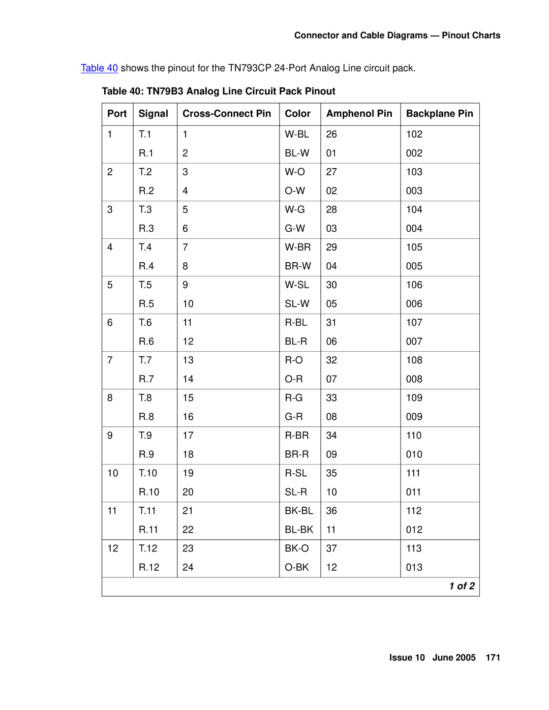
BK-BL
Connector and Cable Diagrams Pinout Charts
BL-BK
BR-V
Processor Interface Cable Pinout Signal
Name Amphenol Connector
Processor Interface Cable Pinout
Port Circuit Pack Lead Designations
Modem Name Amphenol
TXR.2
LI High
\BR
TXR.4
BL-W
SL/V
DIOD2
Circuit Pack and Auxiliary Equipment Classifications
Digital Analog Line Wire Ports
Circuit Pack and Auxiliary Equipment Leads Pinout Charts
Four Pin Line Digital Trunk Trk
LI, LI
Read This First
Contact Network Technicians
Service Interruption
Digit dial plan expansion
Call Management System
Translation Card Upgrade Procedures
Software Upgrade
Usable Circuit Packs
Tasks List
Task Table
Tasks List Task Description
Pre-upgrade checklist
To the RFA Website Pre-upgrade administration changes
Have direct connection
Rk.com
Pre-upgrade administration changes
Remove Print Messages Feature Access Code
Pre-upgrade administration changes
Isdn
Remove print-msgs buttons
Attendant Console
Station Site Data
Abbreviated Dialing
Button Assignments
Processor Channel Assignment
Remove MSA node names
Remove MSA processor channels
AUDIX-MSA Node Names
Remove MET station administration
Check SPE
Verify Software Version
Verify System Status
Disable Scheduled Maintenance and Alarm Origination to Inads
Save Translations
Check Link Status
Save Announcements if necessary
Shut Down Definity Audix System if necessary
Replace Circuit Packs
Install the License File
Pre-installation
Type reset system 3 and press Enter
Display Memory-Configuration
Installation direct connection
Installation no direct connection
Set Daylight Savings Rules
List trunk-group list hunt-group list data-module
Verify the Upgrade
Enable Scheduled Maintenance
Type display alarms and press Enter
Enable Alarm Origination to Inads
Click on the Start Product Registration button
This verification might be done automatically in the future
Page
Type display communication-interface links and press Enter
Power Up Definity Audix System
Restore Announcements if necessary
Check Customer Options
Return Equipment
Install translation card
Save Translations post-upgrade
Save Announcements if necessary- post-upgrade
Type reset system shutdown and press Enter
Definity Audix Power Procedures
Power Down the Audix System
Power Up the Audix System
Page
On an Avaya Definity Server CSI
Software compatibility
Call Management System CMS
Antistatic protection
Wireless systems
Task Description
Configuration license long SAT command
Pre-upgrade checklist
RFA website Pre-upgrade administration changes
Go to the RFA website
GSO
Pre-upgrade administration changes
Remove Print Messages Feature Access Code
Station form
Remove MSA node names
Remove MET station administration
Type status system 1 and press Return
Verify version
Disable scheduled maintenance and alarm origination
Type display errors and press Return
Type change system-parameters maintenance and press Return
Enter display communication-interface links and press Return
Upgrade the software
Install the License File
Administer no-license/emergency numbers
Type change daylight-savings-rules and press Return
Type display alarms and press Return
Type display communication-links and press Return
Type list signaling-group press Return
Enable scheduled maintenance
Click on the Start Product Registration button
This verification might be done automatically in the future
Restore busyouts
Save announcements post-upgrade
Restore announcements
Upgrade Firmware on Programmable Circuit Packs
Add Circuit Packs
Type change circuit-pack
VAL
Self and C-LAN-distributed download procedure
TN771DP
Self download
Prepare for download
Download Method Differences LAN-distributed
Download
DIG-LINE
Verify hardware/software requirements
Type list fiber-link and press Enter
Get circuit pack information
Type add data-module UUC17 and press Enter
Type add data-module UUC33 and press Enter
Upload image file from the Web to staging area
Set up source circuit pack’s file system
FTP the image file to source
Schedule a download to targets
Type change firmware download and press Enter
Firmware download or a status
Directory board command showed
Disable firmware download
Firmware Download fields and descriptions Field Description
Automatically remove the new Download, the procedure
Firmware Download
Monitor download progress
Status Firmware Download
Disable file system
Reseat VAL circuit pack
Type list directory board Uucss and press Enter
Troubleshooting firmware downloads
Testing firmware download
Aborting a firmware download
Backing out of a firmware download
Reverting to an older TN799DP or TN2501AP vintage
Display Firmware Images
Adding or Removing Hardware
Install TN464HP/TN2464CP with Echo Cancellation
Type add change trunk-group next number and press Enter
Trunk Features
Type add change ds1 Uucss and press Enter
DS1 Circuit Pack
CAS
Installation
Add CO, FX, WATS, and Pcol
Requirements
Add Tie Trunks
Add did Trunks
Tie Trunk Circuit Packs Component Side
Add DS1 Tie and OPS
Tie Trunk Option-Switch Settings and Administration
Add Code Calling Access
Add Speech Synthesis
Add Pooled Modem
Type add modem-pool next and press Enter
Settings for Modem Connected to Data Module
Type add data-module next and press Enter
Type add station next and press Enter
Replacing a TN750/B/C circuit pack
Add Integrated Announcements/TN2501AP
Before you start
Announcement File Specifications
Configurations
Caveats
VAL Manager application PC only
Hardware specifications
Recording and storing announcements
FTP client application
Mbps uses Category 5 cable
Backplane Adapter
LAN cable
Mbps uses Category 3 cable
Hardware installation
Switch administration before hardware installation
List configuration board
Administer the IP connections
VAL#1
Change node-names ip
Change ip-interfaces
SPE a IP Node Names
VAL
IP Interfaces
LAN
Medpro
Add data-module
Add ip-route
Data Module
International
Add ISDN-PRI
Test the IP connections
North American
Install Cables
Add Circuit Packs
Enter Added Translations
Disable Alarm Origination
Install Circuit Packs
Add Packet Bus Support
Administer the Bus Bridge
Test the Packet Bus and C-LAN Circuit Pack
Verify Customer Options
Add CallVisor Asai
Enable Asai option
Install cables from TN464HP to the MDF as required
Installing the trunk
Add TTC Japanese 2-Mbit Trunks
Add DCS Interface
Test the Packet Bus and Control-LAN Circuit Pack
Cable Connection for C-LAN
Add the Packet Bus Support
Add ISDN-BRI
Add ISDN-BRI
Add IP Solutions
Add Radio Controller
Add IP Media Processor
Check your onsite equipment
Preparing for Installation and Upgrade
Required Hardware
Check your shipment
Connect the cables for TN799DP
Installing the TN2302AP IP Media Processor
Install the Circuit Packs
Connect the cables for TN2302AP
Connect the Ethernet
TN2302AP IP Interface faceplate
Initial Administration Steps for C-LAN IP Media Processor
Type change node-names and press Enter
Node Names
Type change ip-interfaces and press Enter
Test the External Connection to the LAN
Ping Results
Medpro Pass
Replace the Cables
Pre-upgrade steps
Upgrading TN802 IP Trunking to TN2302AP IP Media Processor
Remove the Circuit Packs
Administration
Medpro
Remove the Circuit Packs
Install the circuit packs
Checking for required components
Installing an Integrated Channel Service Unit Icsu Module
120A3A Channel Service Unit Module
Installing the 120A3A CSU
Adding or Removing Hardware
H600-383 Cable Lengths by Group Number
Installing a J58890CG Power Distribution Unit
Mounting without a backing plate
Mounting with a backing plate
Install terminal server
Installing and administering the terminal server
Required equipment Comcode Description Qty Supplier
Distance limits
Making the connections
Cabling diagram
Connecting an adjunct to the IOLAN+
Administering the IOLAN+
Setting up HyperTerminal on the computer
Navigating the IOLAN+ terminal server
Administering the IOLAN+ the first time
Connections Menu
CLI
Administration Menu
Select Admin mode Password and press Enter
Subnet mask
Server Configuration
Administering the gateway
Rebooting the IOLAN+
Term
Administering an IOLAN+ port
Port Setup Menu
Destination IP address
Access Remote Authentication None Mode Raw Connection None
Speed Monitor DSR Yes Monitor DCD No
Remote Port
Testing
Select Admin mode stats and press Enter twice
Potential failure scenarios and repair actions
Administering IP services
Administering IP node names
Spdu
IP Services
Session Layer Timers
CDR1
Install Call detail recording CDR
Connecting CDR Equipment
Administering CDR Data Collection
Local Node field, enter switch-clan
Administering CDR parameters
CDR Link Status
Testing the switch-to-adjunct link
Primary Output Endpoint field, type CDR1
CDR System Parameters
Install Reliable Data Transport Tool Rdtt Package
Contents of the Rdtt
Downloading the tool
Nonsignaling configuration
Install wideband endpoints
Installing Rdtt
Administering Rdtt
Typical nonsignaling wideband configuration
Signaling configuration
Typical signaling wideband configuration
Install multimedia call handling Mmch
Connect the endpoints
Administer the system
Type y in the Multimedia Early Answer field and press Enter
Expansion services module
Administer the endpoints
Administer one number complex
ESM installation
Administration
Place test call
Troubleshooting
Task list
Connecting printers using TCP/IP
Administering adjunct parameters
Connect printers
Testing the switch-to-adjunct link
System printer
System Printer Endpoint field, type Sysprnt
Install DS1/T1 CPE loopback jack
Installing a loopback jack
With a smart jack
Administering the loopback jack
Loopback testing with a smart jack
Without a smart jack
Busying out the DS1 circuit pack
Testing the DS1 span from the Icsu to the loopback jack
Administering the DS1 for the test
Checking the integrity of local equipment
Running the data test
Testing the integrity of the loopback circuit
Testing the integrity of data sent over the loop
Clearing the results of previous tests
Install DS1/T1 CPE loopback jack
ConditionSolution
Condition Solution
Releasing the DS1 circuit pack
Restoring DS1 administration
Network interface at smart jack for a 120A2 or later Icsu
Install DS1/T1 CPE loopback jack
Testing a loopback jack without a smart jack
Network interface at dumb block for a 120A2 or later Icsu
Adding or Removing Hardware
Configurations using fiber multiplexers
Install Isdn converters and adapters
PRI-to-DASS and PRI-to-DPNSS converters
Converters for single-carrier cabinets
Typical PRI to BRI converter cabling
PRI-to-BRI converter
Converters for multi-carrier cabinets
00221 PDH
Typical 909A/B universal coupler
Install 909A/B universal coupler
BSY2/BY2
Typical modular jack pinout
Malicious call trace
Install malicious call trace
Install music-on-hold
Nonregistered music source
Registered music source
Wiring block must be locally engineered
Install paging and announcement equipment
Loudspeaker paging without paging adapter
Loudspeaker paging
Loudspeaker paging access without universal coupler
Loudspeaker paging with universal coupler
External ringing
Espa radio paging
Other adjunct installation information sources
Queue warning indicator
Intuity Audix Messaging Systems
Avaya EC500 Extension to Cellular and Off-PBX Stations
Avaya Modular Messaging System
Asai and Definity LAN Gateway
Avaya Interactive Response
Troubleshooting Guidelines
Appendix a Troubleshooting an Upgrade
Troubleshooting Upgrades
No Translation After Upgrade
Translation Corruption Detected
Type add data-module PI ext and press Enter
Re-install the ISDN-PRI Links Only for Failed Upgrades
Unsuccessful Translation Backup
Software Incompatibility
Page
Using the ASG Mobile
Appendix B Access Security Gateway
Access Security Gateway
Index
Back-up battery backup translations
RAM
Installing impedance, setting
TN2185 ISDN-BRI
113
TN2464BP/CP
Wiring telephone power supplies