SECTION 2 - OPERATION
Ignition Switch
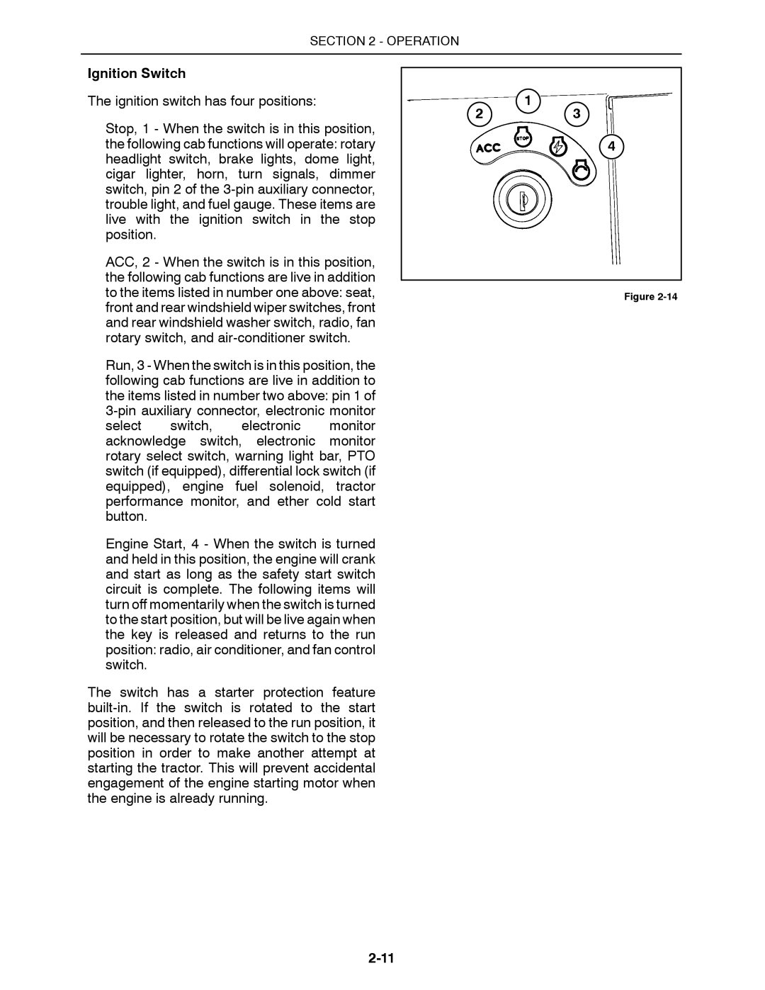
The ignition switch has four positions:
Stop, 1 - When the switch is in this position, the following cab functions will operate: rotary headlight switch, brake lights, dome light, cigar lighter, horn, turn signals, dimmer switch, pin 2 of the
ACC, 2 - When the switch is in this position, the following cab functions are live in addition to the items listed in number one above: seat, front and rear windshield wiper switches, front and rear windshield washer switch, radio, fan rotary switch, and
Run, 3 - When the switch is in this position, the following cab functions are live in addition to the items listed in number two above: pin 1 of
Engine Start, 4 - When the switch is turned and held in this position, the engine will crank and start as long as the safety start switch circuit is complete. The following items will turn off momentarily when the switch is turned to the start position, but will be live again when the key is released and returns to the run position: radio, air conditioner, and fan control switch.
The switch has a starter protection feature
1
23
4
Figure