Page
Improvements
California Emission Control Warranty Statement
Federal Emissions Warranty
Contents
Precautionary Statements Personal Safety
Machine Safety
Tractor
Driving the Tractor
Operating the Tractor
Page
Operating the PTO
Servicing the Tractor
Diesel Fuel
Safety CAB
Safety Decals
Page
Rops Caution Located inside the cab on the rear left post
9702854
Articulation Lock
Additional Safety Items
Alternate Exit
Rops Maintenance and Inspection
Important Do not try to weld or straighten the cab/ROPS
Page
Introduction to this Manual
OPERATOR’S Manual Holder
Tractor Statement of USE
Follow Your OPERATOR’S Manual
Tractor Terminology
Tractor Orientation
Overall Description
General Information
Vehicle Identification Plate
Identification Numbers
Tractor Identification Data
Engine Identification
Tractor Identification
General Information
Quad Shift III Transmission 12x4 Synchronized
Powershift Transmission 12x2 Powershift
Transmission Identification
Front and Rear Axle Identification
Engine Side Covers
Battery Cover
Protective Shielding
Starter Solenoid Shield
Master PTO Shield
Center PTO Articulation Drive Shaft Shield
Band
Tire Configurations
Articulation Stop Spacers Quick Reference Chart
2290
2335
2360
2375
2425
External Lighting
General Information
Controls and Instruments Overview of Location and Function
Forward Operator Controls
Foot and Floor Controls
Overhead Controls
Right Side Console Controls
Additional CAB Controls
General Information
General Information
General Information
Operator Seat Controls
Installation of CAB-MOUNTED Accessories
General Information
General Information
General Information
Bus bar pins are identified as follows
General Information
Precautions Battery Charging
Welding & Battery Charging
Precautions Welding
Towing the Tractor
Hauling the Tractor on a Transporter
PRE-OPERATION Checks
General Information
Section Operation
Introduction
Precautionary Statements
CAB
Entering the CAB
Operation
Right Rear Window
OPERATOR’S Seat
Seat Belt
Seat Adjustments
Page
Steering Wheel Tilt Control
Steering Wheel Telescopic Adjustment
Steering Wheel and Column
OPERATOR’S Control Console
Operation
Ashtray and Cigarette Lighter
Ether Aid Button
Front Windshield Wiper Switch
Rear Window Wiper Switch
Front and Rear Windshield Washer Switch
Engine Coolant Temperature Gauge
Engine Oil Pressure Gauge
Operation
Operation
Right Console
Operation
Articulation Lock
Tractor START-UP and Engine Operation
Engine Starting
Cold-Weather Starting
Operation
Engine Block Heater
Tractor Boosting
Throttle
Cruise Control Operation
Operation
Operation
Heater
Stopping the Tractor
Overhead Climate Controls
Air Conditioning
Pressurizer Vents
Mirror
Radio Optional Equipment
Foot Brake
Braking System
Park Brake
Transmission Operation
Quad Shift III 12 x 4 Operation
Quad Shift III Shifting
Range Shifting
Gear Shifting within a Range
Forward/Reverse Shifting
Powershift Transmission Operation
Powershift Transmission Shifting
Operation
Automatic Range Select
Decelerator Pedal
Differential Lock
Driving the Tractor
Rotary Light Switch
Tractor Lighting
Operation
Operation
Cab Dome Light
Trouble Light
Wide Transport Marker Lights
Roof-Mounted Work Lights Optional
Trailer Socket
Operation
Electronic Monitor Digit Select Switch
Electronic Instrument Control System
Electronic Monitor
Electronic Monitor Acknowledge/Reset Button
Electronic Monitor Rotary Select Switch
Engine and Eics
Engine Derate and Eics Warning Lights
Electronic Engine
Normal Operation Electronic Instrument Control System
Key to the RUN Position Engine Off
Key to the Engine Start Position Engine Cranking
Engine Running Normal Operation
Operation
Operation
Operation
Operation
Operation
Calibrating the Electronic Instrument Control System
Setting the Tire Rolling Radius
Example
Programming Units of Ground Speed Measurement
Service Interval One Reset
Service Interval One Alarm Reset
Service Interval Two Reset
Service Interval Two Alarm Reset
Setting the Final Drive Ratio
Setting the Transmission Output Shaft Gear Profile
Engine
QSM11
Low Transmission Lube Pressure
Transmission Lubrication Filter Bypass
Hydraulic System Filter Bypass
Low Engine Oil Pressure below 100 kPa 15 psi
Operation
Operation
Operation
Low Coolant Level
Operation
High Engine Coolant Temperature
Operation
Operation
Electrical System High/Low Voltage
Operation
Fuel Level
Operation
Transmission Speed Sensor Failures
Park Brake Alert
Electronic Monitor Rotary Select Switch Failures
Engine Overspeed Condition
Yellow and Red Engine Warning Lights
Operation
Additional Features Electronic Instrument Control System
Operation
Operation
Operation
Operation
Operation
Engine Diagnostics
100
101
Description and Operation
Transmission Output Shaft Sensor Actual
Page
103
Implement Status Switch
OPERATOR’S Controls
Page
Caret 2/ Pos. B
Slip Alarm
Caret 1/ Pos. a Acre accumulator
Caret 3/ Pos. C Distance Accumulator Feet
Page
Page
Page
Page
Implement Status Switch
110
111
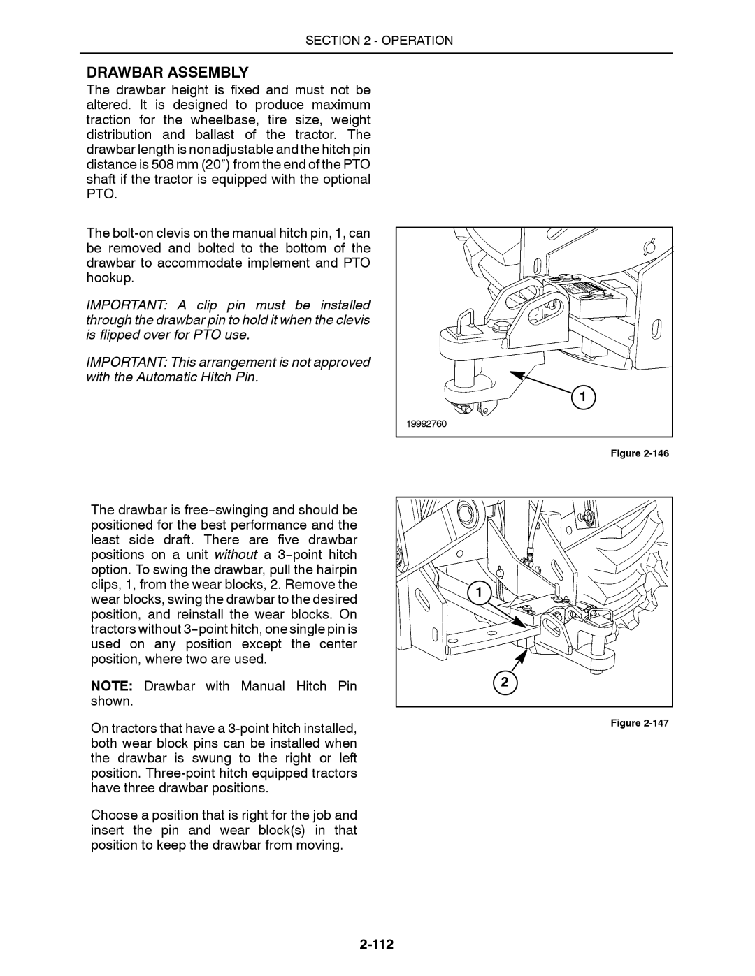
Drawbar Assembly
112
113
Drawbar with Manual Hitch PIN
Proper Drawbar PIN Latch Operation
Drawbar with Automatic Hitch PIN
114
115
Drawbar Loading
Implement Transport
117
PTO Operation
118
PTO Operation
119
120
121
122
123
Hydraulic System Operation
Hydraulic System
Page
125
Remote Control Operation
126
Lockout Levers
127
Flow Control Adjustment
128
Pressure Release Detent Adjustment
129
130
Quick Couplers
Coupler Connection
131
132
Bleeding Remote Cylinders
Operating Continuous Flow Hydraulic Equipment
133
Hydraulic Motor Applications
134
19 mm 3/4″ Coupler Kit P/N
Optional Hydraulic Equipment
Point Hitch Description
135
136
Automatic Raise/Lower Switch
Point Hitch Controls
137
Manual Raise/Lower Switch
Rotary Depth Control Knob
138
Rate of Hitch Raise Adjustment
Rotary Lowering Rate Control Knob
Lift Links
Hitch Adjustments
Lower Links
Upper Link
Shims
140
141
Float Mechanical
Sway Blocks
142
Drawbar Positioning
PTO Option
Category Conversion
143
144
145
Quick Hitch Installation Optional Category III/IVN
Implement and Tractor When Backing UP
146
Implement Connection
Implement Disconnect
Feedback Potentiometer
147
148
Semi-integral Implements
Implement HOOK-UP
Point Hitch Implements
149
Point Hitch Operation
150
151
152
Factors Determining Best Tire Performance
Tires and Articulation Blocks
Proper Tire Selection
153
Articulation Blocks
154
155
Application and Ballasting
Ballasting
Basic Rules of Thumb for Ballasting
Loads Matched to the Tractor
157
Too Little Ballast
Too Much Ballast
158
Tractor Weight Distribution
Rolling Resistance
Operating Weight and Fore/Aft Ratio
Shipping Weight and Fore/Aft Ratio
Unballasted Shipping Weight
Calculation of Ballast
160
Weights
Additional Ballast Requirements
161
Every 500 Hours
Clean the Fuel Tank Vent
Clean the Hydraulic Suction Screen
Operation
162
163
164
Maximum Operating Weight
Maximum weight
165
TOOLBOX/STORAGE Tray
Toolbox
Engine BREAK-IN
BREAK-IN Periods
BREAK-IN Period
166
General Information
Fueling the Tractor
Fuel Storage
Fuel Requirements
Adding Diesel Fuel
Removing the Hood Panels
Engine Access
Opening the Hood Panels
Front Grille
Battery Access
Remote Valve Access
Blank
Page
Page
Every 10 Hours or Daily
2425 Tractors
Page
Every 10 Hours or Daily
Ethylene Glycol Propylene Glycol
82 F
Check the Fan Belt Tension
Every 10 Hours or Daily
Check Air-Conditioner Compressor Belt Tension
2290, 2335, 2375 QSM11 Engine
2425 N14 Engine
2360, 2425 N14 Engine
Check the Engine Oil Level
2290, 2335, 2375 QSM11, 2360 and 2425 N14 Engine
Drain the Fuel Filter
Check the Hydraulic Oil Level
Check the Transmission Oil Level
Check the Brake Reservoir Level
Brake Adjustment
Lubricate the Optional 3-Point Hitch
Lubricate the Front Steering Cylinder Pins
Lubricate the Lower Articulation Pin
Lubricate the Upper Articulation Pin
Lubricate the Rear Steering Cylinder Pins
Lubricate the Front Drag Link Pins
Lubricate the Rear Axle Drive Shaft Steady Bearing
Lubricate the Rear Drag Link Pins
Reminder
Check the Engine Air Cleaner Connections
Every 50 Hours
Clean the Cab Air Filter
Method a
Method B
Check the Differential Oil Level
Check the Planetary Hub Oil Level
Check Tire Air Pressure
Every 250 Hours
Change the Engine Oil and Filter
2290, 2335, 2375 QSM11
2360, 2425 N14
Change the Coolant System Filter
Check the Engine DCA4 Protection Level
Change the Fuel Filter
Check the Air-Conditioner Sight Glass
Check the Weight Kit Hardware Torque Optional
Check the Air-Conditioner Drain Hoses
Configuration Torques
Check the Wheel Hardware Torque
Driveline Cross and Bearing Lubrication
Page
Clean the Battery Connections
Check the Battery Electrolyte Level
Check the Starter Battery Connections
Clean the Engine Air Precleaner
Clean the Hydraulic Reservoir Breather
Change the Hydraulic Filter
Change the Transmission Filter
Change the Differential Oil
Change the Planetary Hub Oil
Check the Axle Mount Bolt Torque
Check the Drawbar Wear Blocks
Page
Change the Engine Inner and Outer Air Cleaner Elements
Every 1000 Hours
Change the Cab Air Filter
Every 1000 Hours
Every 1500 Hours or Yearly
Change the Transmission Oil
Every 1500 Hours or Yearly
Every 1500 Hours or Yearly
Check the Transmission Mounts
Change the Hydraulic Oil
Check the engine mounts
Check the Engine Turbocharger Connections
Check the Radiator and Heating System Hoses
Check the Cab Mounts
Every 2000 Hours or 2 Years
Change the Engine Coolant
Every 2000 Hours or 2 Years
Ethylene Glycol Propylene Glycol
Clean the Engine Air Cleaner Outer Element
Indicated by Warning Light
Indicated by Warning Light
Headlight/Work Lights Bulb Replacement
AS Required
Change the Roof Warning Light Bulbs
Change the Brake Light Bulbs
Change Fuses/Relays
IGN
Check the Throttle Settings
Clean the Cab Seat and Upholstery
Adjust the Decelerator Pedal Setting
Clean the Cab Floor
Check the Windshield Washer Fluid
Change the Windshield Wiper Blades
Change the Brake Fluid
Change the Ether Canister
Drain the Fuel Tanks
Wheel Installation
Articulation Blocks
AS Required
Rear Fender Height Adjustment
SINGLE, Dual and Triple Wheel Installation
Special Tie Rod style dual wheels 32″ dual wheels
AS Required
Standard Tie Rod Style Dual Wheels
AS Required
AS Required
Reminder
Standard Drum-Style Triple Wheels
AS Required
AS Required
Removal from Storage
Storing the Tractor Preparation
Storing
Initial Engine Start-up
Section Troubleshooting
Troubleshooting Chart
Troubleshooting
Engine
Troubleshooting
Troubleshooting
12x2 Powershift Transmission
Transmission
12x4 Quad Shift III and 12x2 Powershift
Electrical System
Open
Hydraulic System
Point Hitch
Brakes
CAB
Tractor Performance Monitor
Electronic Instrument Control System
Power TAKE-OFF PTO
Operation
Blank
Section Specifications
Tire Size Height To Top
Overall Widths
700/65 R38 Special Duals Drum
Wheel Tread Width
20.8 R38 R1 Radial
900/50 R42 R1W
Articulation Angle
Model
Base Tractor Weight
Tire Weights
1136.3 2272.5 Radial Drum Row Crop 18.4 R38
Effect on Front Axle Effect on Rear Axle Kg lbs
Example
Optional Transmission and Axle Weights
Diesel Fuel
Engine
2360 2425
Engine AIR Intake and Exhaust
Transmission
Specifications Drivelines Component
Specifications AXLES/DIFFERENTIALS
Brakes
Electrical
Capacities
LUBRICANTS/FLUIDS
Speed Chart
Speeds AT 2100 Engine RPM Km/h MPH
Liquid Ballast Table
Measure
Inflation Pressure PSI 18.4 R38
710/70 R38
Metric Measure
Specifications
Tire Loaded Radius
Replacement Bulbs Description BVI Bulb Number
Optional Equipment
Deluxe Radio with Premium Cassette/Weather Band
Blank
Identification HEX CAP Screws and Carriage Bolts
Hardware Torque Values
Minimum Hardware Tightening Torques
HEX Nuts and Locknuts
Identification CAP Screws and Carriage Bolts
Locknuts
Index
Equipment -132 Operating remote equipment
Transmission -6 Troubleshooting, 12x4 Quad Shift
Delivery Report
Dealer Copy
Page
Owner Copy
Page
Check and ADJUST, AS Required
Description
Service Performed
Description
Check engine water pump belt tension
Service Performed
Publications Order Form
Dealer Order Only
Dealer Order Information
II. Owner Information
California
Proposition 65 Warning