TeamPoS 3000 XL and XL2 | Maintenance |
Caution: Ports designated as Port C on the backplane (24V PUSB) and Port 3 on the Combo board (24V RS232) do not meet UL limited power source (LPS) requirements. These ports are limited to only allowing 24V Retail POS RS232 or powered USB peripherals that do not exceed a rated current of 4 Amps.
Peripherals intended to be connected via - Jacketed Cable for external use rated 30 V, max 3.05m long, marked
Caution: Be sure to observe all ESD precautions and power off procedures.
The Powered USB I/O board has 3, 12V powered USB connections, which are installed in the top slot of the backplane assembly and cannot be used in combination with any of the other I/O boards. A blanking plate fills in the short slot.
1.Remove the back panel (See Section 5.1.2).
2.Disconnect the power cable from the back of the controller.
3.Remove the front panel (See Section 5.1.1). The yellow LED should be off (See Section 1.2).
4.Unseat the motherboard (See Section 7.2).
5.Remove the backplane assembly (See Section 7.8).
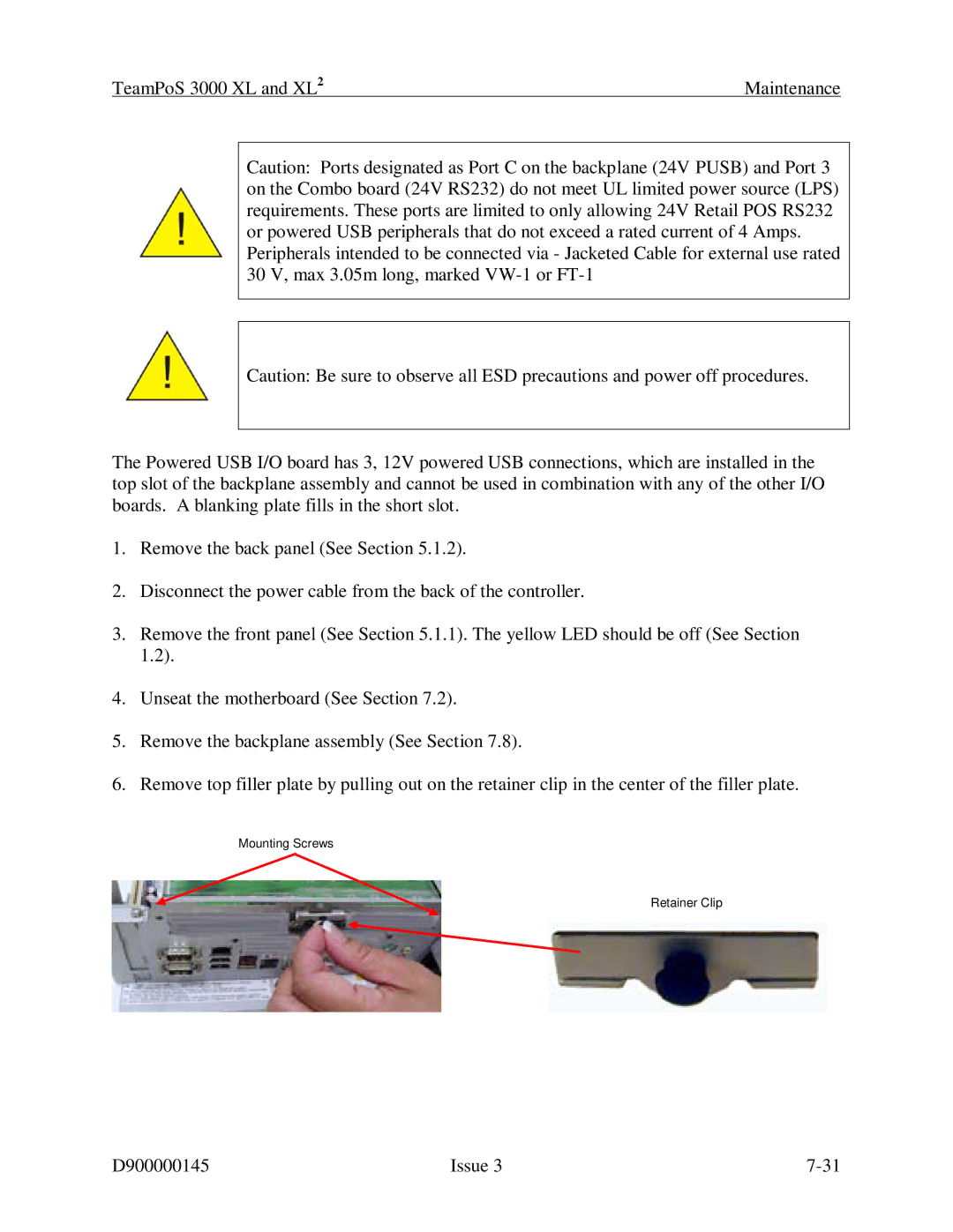
6.Remove top filler plate by pulling out on the retainer clip in the center of the filler plate.
Mounting Screws
Retainer Clip
D900000145 | Issue 3 |