TeamPoS 3000 XL and XL2 | Installation |
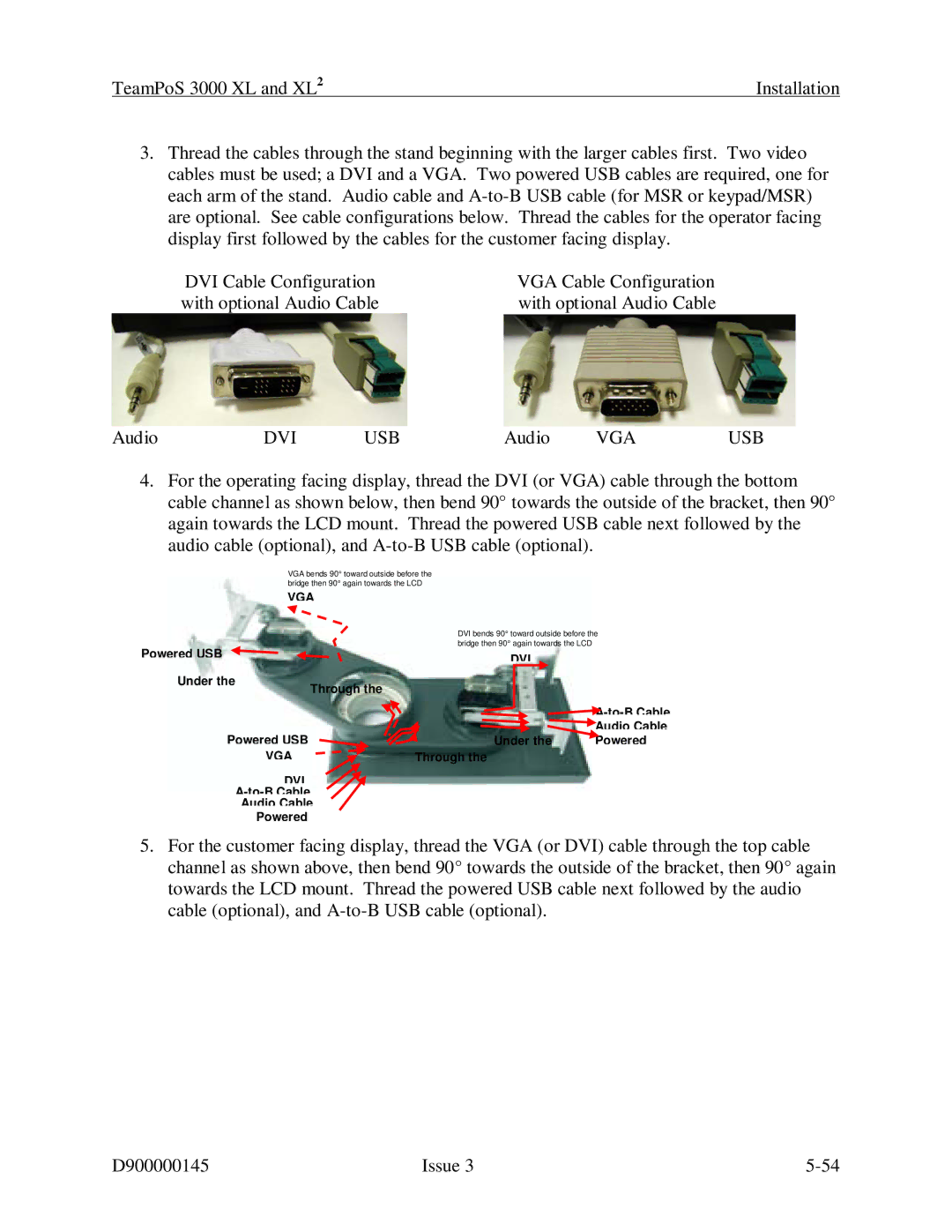
3.Thread the cables through the stand beginning with the larger cables first. Two video cables must be used; a DVI and a VGA. Two powered USB cables are required, one for each arm of the stand. Audio cable and
DVI Cable Configuration | VGA Cable Configuration |
with optional Audio Cable | with optional Audio Cable |
Audio | DVI | USB | Audio | VGA | USB |
4.For the operating facing display, thread the DVI (or VGA) cable through the bottom cable channel as shown below, then bend 90° towards the outside of the bracket, then 90° again towards the LCD mount. Thread the powered USB cable next followed by the audio cable (optional), and
VGA bends 90° toward outside before the bridge then 90° again towards the LCD
VGA
Powered USB |
|
Under the | Through the |
|
Powered USB
VGA
DVI
Audio Cable
Powered
DVI bends 90° toward outside before the bridge then 90° again towards the LCD
DVI
![]() A-to-B
A-to-B
![]() Audio Cable
Audio Cable
Under the | Powered |
Through the
5.For the customer facing display, thread the VGA (or DVI) cable through the top cable channel as shown above, then bend 90° towards the outside of the bracket, then 90° again towards the LCD mount. Thread the powered USB cable next followed by the audio cable (optional), and
D900000145 | Issue 3 |