Manuals
/
Fujitsu
/
Computer Equipment
/
Typewriter
Fujitsu
manual
TeamPoS 3000 XL and XL2 Installation D900000145 Issue
Models:
3000 XL
1
98
252
252
Download
252 pages
9.74 Kb
95
96
97
98
99
100
101
102
Troubleshooting
Specifications
Install
Parts list
Combo Board Diagram
Printer PTR Connector signals
Printing errors
Dimension
Maintenance
Issue Date Revision
Page 98
Image 98
TeamPoS 3000 XL and XL
2
Installation
D900000145
Issue 3
5-52
Page 97
Page 99
Page 98
Image 98
Page 97
Page 99
Contents
TeamPoS 3000 XL and XL2
Installation and Maintenance Manual
Issue Date Revision
Lead Acid Battery Hazardous Voltage
Regulatory Information
D90000145 Issue Viii
Table of Contents
Preparing for Installation Determining Power Requirements
Page
10.1 Opening Cmos Setup Screen
10.1.12 USB Feature Setup XL2 Motherboard
Overview
TeamPoS 3000 Control Unit Flow Diagram XL Motherboard only
XL Motherboard
Front Panel LEDs and Switches
Do not use
TeamPoS 3000 Front Panel Switch and LCD Matrix
LED
Intelligent PINs Product Identification Numbers
CPU
This Page Intentionally Left Blank
Environmental Specifications
Environmental Specifications for both XL and XL2
Environmental Specifications
Page
Dimensions
Model D22 & D25 LCD in Dual Stacked Configuration
Model D25 & D25IR LCD in Dual Stacked Configuration
Control Units
Keyboards Model 133 UQ Keyboard Dimensions
Model 133 AU Keyboard Dimensions
Model 92U Keyboard Dimension
Cash Drawers Model TP15 Cash Drawer Standard
Standard Cash Drawer in Open Position D900000145 Issue
Model TP5C Cash Drawer Compact
Displays Model D22 LCD and Model D25 LCD Displays
LCD Vesa Bracket Mounting
Model D22 & D25 LCD’s on Stacked Stand
Model D22 & D25 LCD’s w/MSR
450 17 ¾ 415 355 280 16 3/8
Model D22 & D25 LCD on Dual Stacked Stand
Model D25 & D25 on Dual Stacked Stand
Model D22 & D22 on Dual Stacked Stand
10 VF60 Customer Display stacked
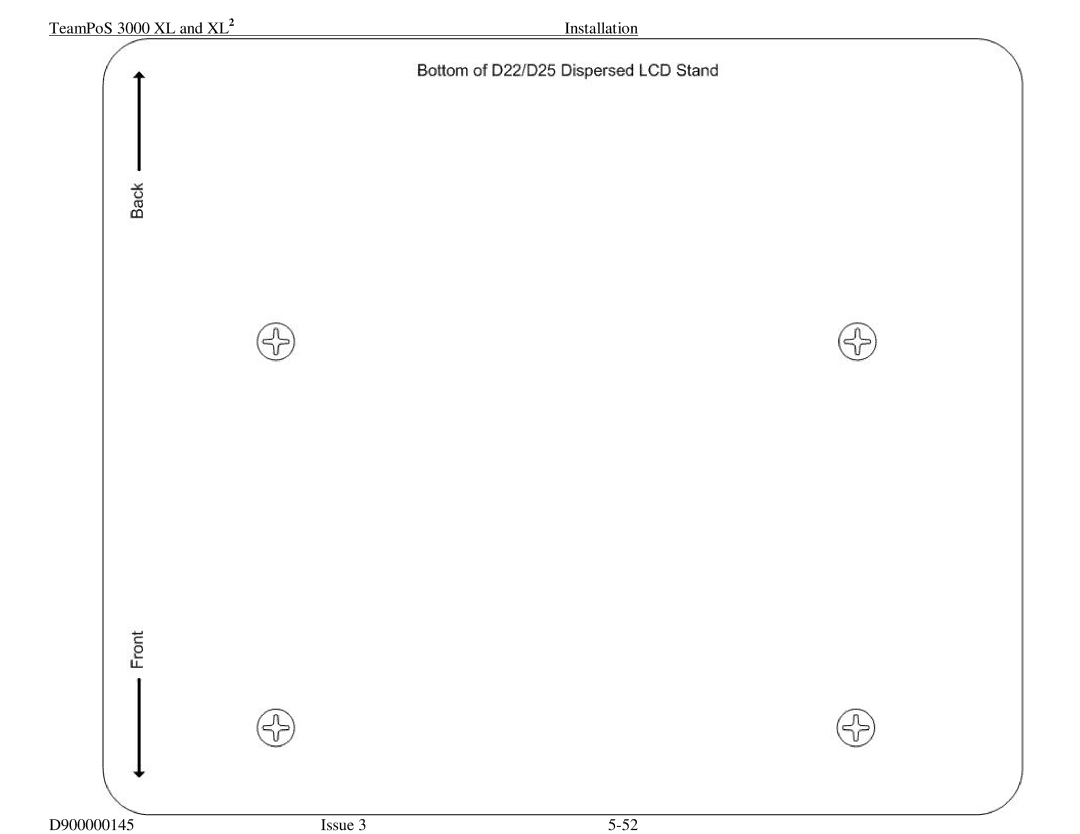
Model D22 & D25 LCD on Dispersed Stands
D22
11 VF60 Customer Display dispersed
Model CT10 Printer
Printers
Model DT50III Printer
This page intentionally left blank
Site Preparation
Returning Equipment
Using Anti-static Protection
Reporting Shipment Damage
Preparing for Installation
Determining Power Requirements
General Requirements
Page
Installation with Other Equipment
Terminals at 100-240 volts
Mains Power Cables
Interior of the front panel of the control unit
Back View of control unit Bottom of the TeamPoS Controller
Panel Removal/Installation Process
Front Panel
Thumbscrew Locking Tab
Rear Panel
Removing the motherboard assembly
Page
Installing CPU and Heat Sink
TeamPoS 3000 XL and XL Installation
Installing the Hard Disk Drives
Page
Installing Memory XL Motherboard only
Page
Installing Memory XL2 Memory
Memory Sockets
Page
Installing the CD/DVD Drive
Issue D900000145
Cosmetic Filler
Installing the Partial Backup Battery
Page
Removing the Backplane Assembly
Locking Screw
Installing PCI Add-In Cards
PCI Connector
Installing the I/O Boards
No I/O Board
Powered USB I/O Board
Mounting Screws Filler Plate Retainer clip
Page
Combo Board
Page
Cable Ports J10 J11 J13 Narrow Ribbon Cable to J12
Page
Combo Board with COM Board XL Motherboard only
Page
Narrow Ribbon Cable J12Cable Ports J13 J11 J10
Ribbon Cable for Com Board Connects to Combo Board
Page
Port Labels
Port Identification
Standard Bracket Locations
Installing the LCD Stands
Single Stacked LCD Stand
D900000145 Issue
VGA
DVI
TeamPoS 3000 XL and XL Installation Typical VGA Cabling
Page
Single Dispersed LCD Stand
DVI USB
D900000145 Issue
Typical VGA Cabling
Mounting Screws
Page
TeamPoS 3000 XL and XL2 Installation D900000145 Issue
Dual Stacked LCD Stand
VGA USB
Audio
Page
No Touch Configuration Touch Configuration with Y-cable
14.4 DVI15 LCD
Audio Separate Power Supply Cable
DV15 ready for Vesa mounting
POS I/F USB
Page
Page
Page
Installing the MSR or Keypad/MSR
Latch
Keycaps installed
Installing the VF60 in Stacked Stand
Page
Use screw to
Removal of round
Page
Stacking the LCD Monitor
Page
Page
Installing the Central Filler and Keyboard
AU Keyboard D900000145 Issue
Page
Installing the Central Filler
Installing the Printer I/O Board DT50 Series only
Page
Stacking the Printers
Stacking the DT50 Series Printer
Push Backwards
Stacking the CT10 Printer
Slide to the right
Page
General Care and Maintenance
System Operations
Power on and OFF Sequence
Powering on
Powering OFF
Maintenance
Periodic Maintenance
TeamPoS 3000 XL and XL Maintenance
Powering OFF
Replacing the Motherboard
Page
Screws Disconnect operator Cable
Page
XL Motherboard Layout
XL Motherboard Settings
JP5
Picture of XL Motherboard TP3000 Motherboard
Sata 2SW
4 XL2 Motherboard Layout
Sata
TeamPoS 3000 XL and XL2 Maintenance
5 XL2 Motherboard Settings
Photo of XL2 Motherboard
Replacing the CPU and Heat Sink
Align arrows here
Replacing the Hard Disk Drives
Page
Page
Adding or Replacing XL2 Motherboard Memory
Page
Page
Replacing the CD/DVD Drive
Power Connectors Hook Tabs
White Power Connector Ribbon Cable Goes Here
Replacing Battery Backup
White Power Cable
Removing the backplane assembly
Page
Replacing I/O boards
Powered USB I/O Board
No I/O Board
Mounting Screws Retainer Clip
Page
Page
USB Board Jumper Settings
JP3, 4 & 5 Power Source +5V +5VSB Standby Power always on
Combo Board
Page
Combo Board Installation
Page
Combo Board Diagram
COM OUT JP3 JP2 JP1
Combo Board Jumper Settings
11-12
Combo Board picture
Combo Board COM 4 Port Connector Signals
DSR RTS CTS
Printer PTR Connector signals
Combo Board with COM Board XL Motherboard only
Page
Page
Page
Page
COM Board Connectors XL Motherboard only
COM Board Jumpers
Replacing PCI Add-In Cards
Page
Replacing the Power Supply
Page
Replacing the Power Supply Fan
Power Supply Fan mounting screws
Power Supply Fan Connector
Replacing the Backplane
Page
Hex Standoffs
Page
Backplane Jumpers & Connectors
= Normal +5V
TeamPoS 3000 Pin Assignments Backplane
Cash Drawer Plug
This Page Intentionally Left Blank
Troubleshooting
System will not boot up
System fails to start up even though the power is turned on
Display drivers wrong or not installed
Display/LCD is blank at all times
Check item Judgment Action
Printing errors
Check items Judgment Action
Impossible to input data from keyboard and/or abnormal input
Check item Judgment Action
Keyboard MSR reading error
Cash Drawer Operation errors
Customer display errors
Check item Judgment Action
Operation errors of other peripheral devices
Opening Cmos Setup Screen
Cmos Settings
Factory Default Settings
Main Menu Motherboard
Standard Cmos Setup Motherboard
Selection
Bios Features Setup Motherboard
Hard Disk
CPU Feature Setup Motherboard
Selection
Hard Disk Boot Priority Motherboard
Advance Chipset Features Setup- Motherboard
On-Chip VGA Setting
Integrated Peripherals Setup Motherboard
USB Configuration Setup Motherboard
OnChip IDE Device Setup Motherboard
Onboard Device Setup Motherboard
SuperIO Device Setup Motherboard
Power Management Setup Motherboard
Dateof Month Alarm Timehhmmss Alarm
14 PnP/PCI Configurations Setup Motherboard
Frequency/Voltage Control Setup Motherboard
Hardware Monitoring Setup Motherboard
RPM
Event Log Setup Motherboard
Others Motherboard
System Information Motherboard
Set Supervisor/User Passwords Motherboard
This page intentionally left blank
Bios Setup Procedures XL2 Motherboard
Advanced Security TPM State Power Boot Exit
Main Menu XL2 Motherboard
IDE Primary/Master Setup XL2 Motherboard
Standard
Sata Port 1 Setup XL2 Motherboard
Select Item +Change Values Setup Defaults
Sata Port 2 Setup XL2 Motherboard
Sata Port 3 Setup XL2 Motherboard
Advanced Main Menu XL2 Motherboard
Item Specific Help
CPU Feature Setup XL2 Motherboard
10.1.10. GM965 Feature Setup XL2 Motherboard
ICH8MDO Feature Setup XL2 Motherboard
ICH8 IDE
USB Feature Setup XL2 Motherboard
ICH8 USB#5
ICH Sata Pata Control Sub-Menu Setup XL2 Motherboard
Super IO Feature Setup XL2 Motherboard
Hardware Monitor Feature Setup XL2 Motherboard
Security TPM State Power Boot Exit
Other Feature Setup XL2 Motherboard
Security Setup XL2 Motherboard
TPM State Setup XL2 Motherboard
Power Setup XL2 Motherboard
Boot Setup XL2 Motherboard
Exit Select Item Change Values Setup Defaults
Exit Menu XL2 Motherboard
Spare and Upgrade Parts List
D900000145 Issue 11-2
D900000145 Issue 11-3
D900000145 Issue 11-4
D900000145 Issue 11-5
D900000145 Issue 11-6
D900000145 Issue 11-7
D900000145 Issue 11-8
D900000145 Issue 11-9
Top
Page
Image
Contents