TeamPoS 3000 XL and XL2 | Installation |
The Powered USB I/O board has 3, 12V powered USB connections installed in the top slot (the long slot).
1.Remove the rear panel. (See Section 5.1.2).
2.Disconnect the AC power cord from the controller.
3.Remove the front panel (See Section 5.1.1.).
4.Unseat the motherboard (See Section 5.2.).
5.Remove the backplane assembly (See Section 5.9.).
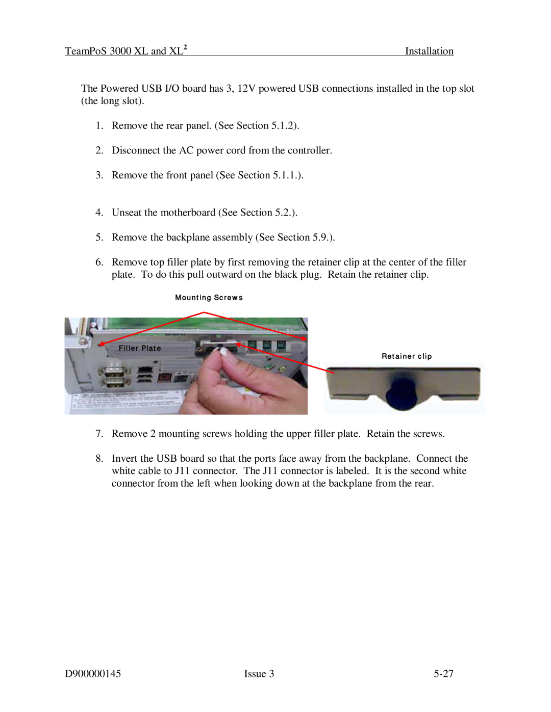
6.Remove top filler plate by first removing the retainer clip at the center of the filler plate. To do this pull outward on the black plug. Retain the retainer clip.
Mounting Screws
Filler Plate
Retainer clip
7.Remove 2 mounting screws holding the upper filler plate. Retain the screws.
8.Invert the USB board so that the ports face away from the backplane. Connect the white cable to J11 connector. The J11 connector is labeled. It is the second white connector from the left when looking down at the backplane from the rear.
D900000145 | Issue 3 |