TeamPoS 3000 XL and XL2 | Installation |
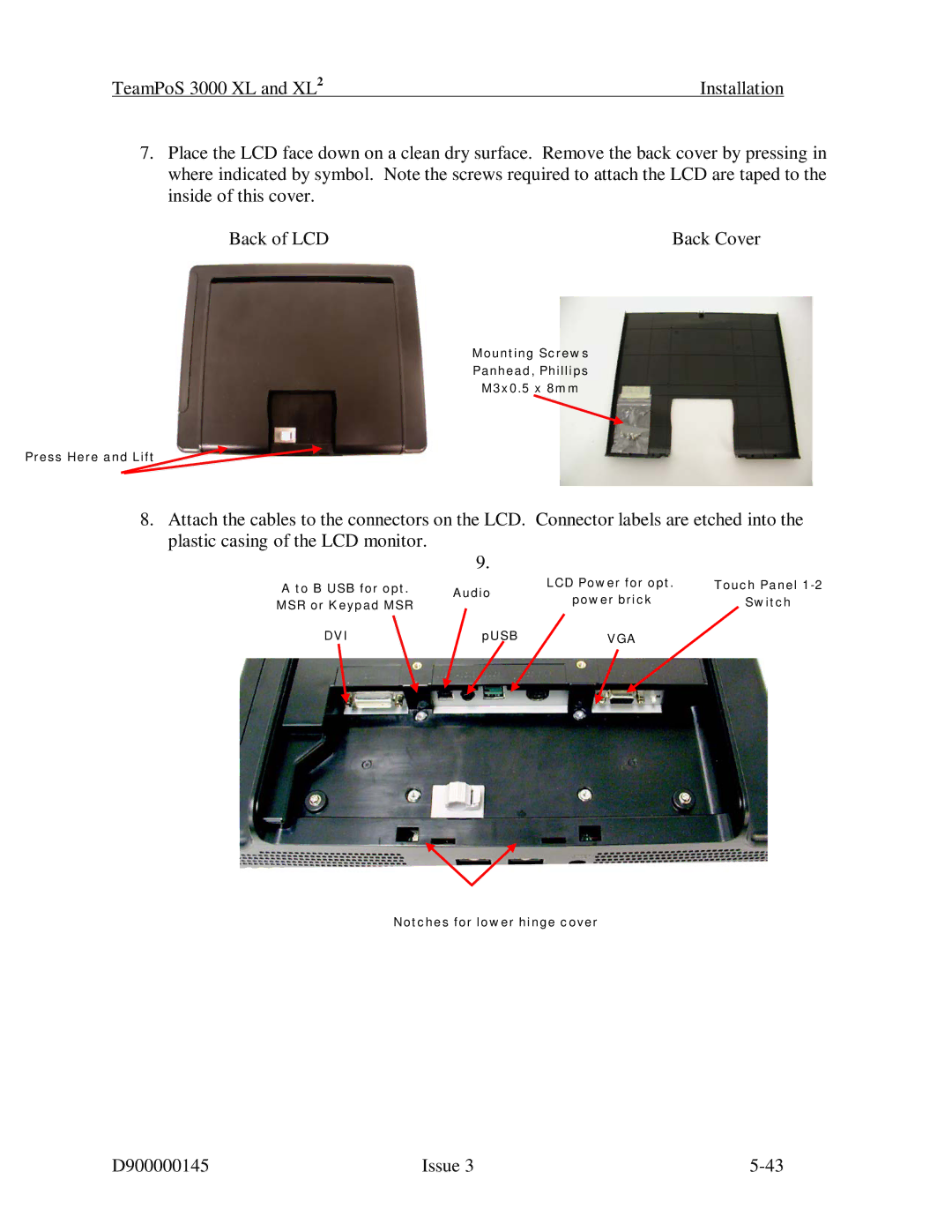
7.Place the LCD face down on a clean dry surface. Remove the back cover by pressing in where indicated by symbol. Note the screws required to attach the LCD are taped to the inside of this cover.
Back of LCD | Back Cover |
Mounting Screws
Panhead, Phillips
M3x0.5 x 8mm
Press Here and Lift
8.Attach the cables to the connectors on the LCD. Connector labels are etched into the plastic casing of the LCD monitor.
9.
A to B USB for opt. | Audio | LCD Power for opt. | Touch Panel | |
MSR or Keypad MSR | power brick | Switch | ||
| ||||
DVI | pUSB | VGA |
|
Notches for lower hinge cover
D900000145 | Issue 3 |