Intel 80287, 80286 manual Virtual Addresses, Format of the Segment Selector Component

Models: 80287 80286

1 515
Download 515 pages 45.04 Kb
Page 112
Image 112

MEMORY MANAGEMENT AND VIRTUAL ADDRESSING

is sufficient to think of a task as an ongoing process, or execution path, that is dedicated to a particular function. In a multi-user time-sharing environment, for example, the processing required to interact with a particular user may be considered as a single task, functionally independent of the other tasks (i.e., users) in the system.

6.2 VIRTUAL ADDRESSES

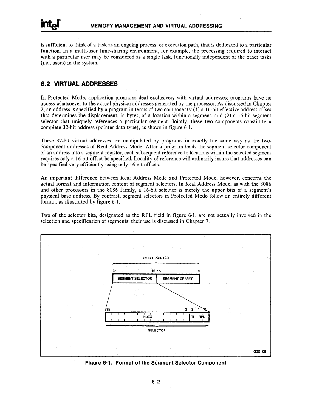
In Protected Mode, application programs deal exclusively with virtual addresses; programs have no access whatsoever to the actual physical addresses generated by the processor. As discussed in Chapter 2, an address is specified by a program in terms of two components: (l) a l6-bit effective address offset that determines the displacement, in bytes, of a location within a segment; and (2) a 16-bit segment selector that uniquely references a particular segment. Jointly, these two components constitute a complete 32-bit address (pointer data type), as shown in figure 6-1.

These 32-bit virtual addresses are manipulated by programs in exactly the same way as the two- component addresses of Real Address Mode. After a program loads the segment selector component of an address into a segment register, each subsequent reference to locations within the selected segment requires only a 16-bit offset be specified. Locality of reference will ordinarily insure that addresses can be specified very efficiently using only l6-bit offsets.

An important difference between Real Address Mode and Protected Mode, however, concerns the actual format and information content of segment selectors. In Real Address Mode, as with the 8086 and other processors in the 8086 family, a 16-bit selector is merely the upper bits of a segment's physical base address. By contrast, segment selectors in Protected Mode follow an entirely different format, as illustrated by figure 6-1.

Two of the selector bits, designated as the RPL field in figure 6-1, are not actually involved in the selection and specification of segments; their use is discussed in Chapter 7.

32-BIT POINTER

16 15

o

SEGMENT SELECTOR SEGMENT OFFSET

i I I I I I INDEX

I! . I

SELECTOR

G30108

Figure 6-1. Format of the Segment Selector Component

6-2

Page 112
Image 112
Intel 80287, 80286 manual Virtual Addresses, Format of the Segment Selector Component