MEMORY MANAGEMENT AND VIRTUAL ADDRESSING,
SEGMENT ADDRESS TRANSLATION REGISTERS | |
|
|
|
|
|
| I,~_,m''''~'" |
|
|
|
|
|
| DATA SEGMENT REGISTER |
|
|
|
|
|
| EXTRA SEGMENT REGISTER |
|
|
|
|
|
| STACK SEGMENT REGISTER |
| 63 | 48 47 | 4039 | 16 15 | 0 | |
|
| ACCESS | SEGMENT BASE | SEGMENT |
| |
|
| RIGHTS | ADDRESS | SIZE |
| |
SYSTEM ADDRESS REGISTERS |
|
|
|
| ||
GDTR | ||||||
|
| 40 BIT EXPLICIT REGISTER |
|
| ||
IDTR _ |
|
|
| INTERRUPT DESCRIPTOR TABLE REGISTER | ||
| 39 |
|
| 16 15 | o |
|
|
| BASE |
| LIMIT |
|
|
|
| ILOCAL DESCRIPTOR TABLE REGISTER | ||||
| SELECTOR | (AUTOMATICALLY LOADED FROM LDTR WITHIN GDT) | ||||
| ||||||
|
|
|
| BASE | LIMIT |
|
G30108
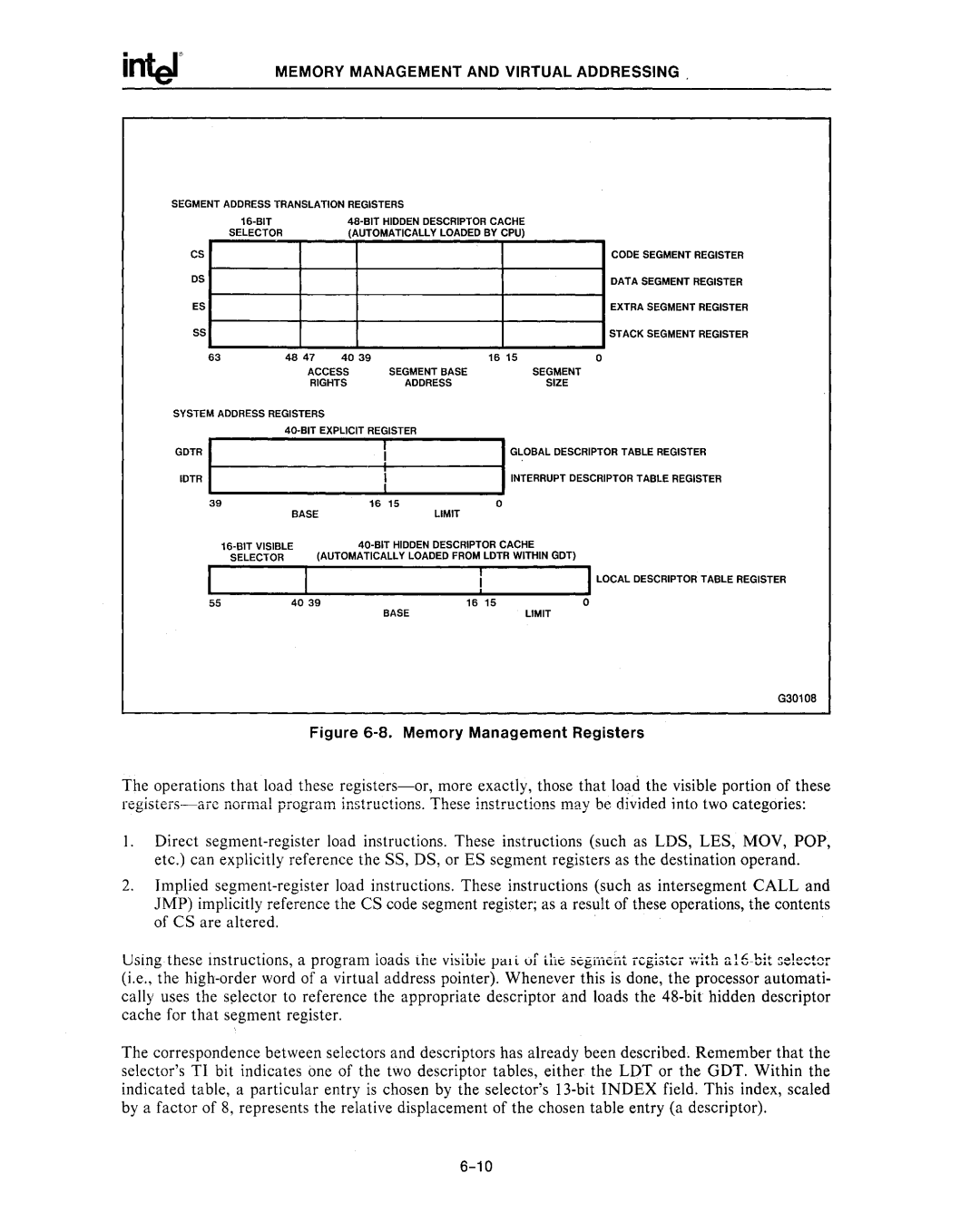
Figure 6-8. Memory Management Registers
The operations that load these
I, Direct
etc.) can explicitly reference the SS, DS, or ES segment registers as the destination operand_
2.Implied
Using these instructions, a program loads ine visiul~ pal i (If the s6giTierll register
(i.e., the
The correspondence between selectors and descriptors has already been described. Remember that the selector's TI bit indicates one of the two descriptor tables, either the LDT or the GDT. Within the indicated table, a particular entry is chosen by the selector's