80286 BASE ARCHITECTURE
STATUS FLAGS: |
|
|
|
|
|
|
|
|
| |
, | ||||||||||
PARITY |
|
| ||||||||
AUXILIARY CARRY |
|
| ||||||||
|
|
|
| I |
| |||||
SIGN |
|
|
|
|
|
| ||||
OVERFLOW |
|
| 12 ~11 10 |
| I |
|
|
|
| o |
15 | 14 | 13 | 9 | B 7 | 6 | 5 | 4 | 3 2 1 | ||
FLAGS: _ | NT | 10rL | OF I OF | IF | I TF I SF | I ZF | _ | AF | _ |
|
|
|
|
| )1 | ::7~;~" |
|
|
| ||
|
|
|
|
|
| INTERRUPT ENABLE |
|
| ||
|
|
| ' | DIRECTION FLAG |
|
|
| |||
SPECIAL FIELDS:
'
'
_ | INTEL RESERVED |
G30108
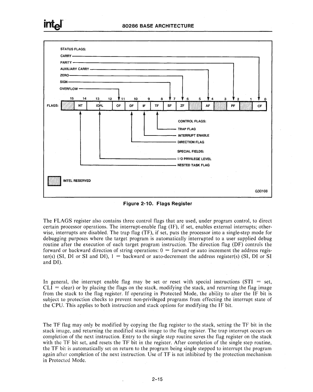
Figure 2-10. Flags Register
The FLAGS register also contains three control flags that are used, under program control, to direct certain processor operations. The
In general, the interrupt enable flag may be set or reset with special instructions (STI = set, CLI = clear) or by placing the flags on the stack, modifying the stack, and returning the flag image from the stack to the flag register. If operating in Protected Mode, the ability to alter the IF bit is subject to protection checks to prevent non·privileged programs from effecting the interrupt state of the CPU. This applies to both instruction and stack options for modifying the IF bit.
The TF flag may only be modified by copying the flag register to the stack, setting the TF bit in the stack image, and returning the modified stack image to the flag register. The trap interrupt occurs on completion of the next instruction. Entry to the single step routine saves the flag register on the stack with the TF bit set, and resets the TF bit in the register. After completion of the single step routine, the TF bit is automatically set on return to the program being single stepped to interrupt the program again arkr completion of the next instruction. Use of TF is not inhibited by the protection mechanism in Proteckd Mode.