PROTECTION
BITSNAME
2TABLE INDICATOR (TI)
SELECTOR
I~~~/do I I LJ. ITI~~
8 | 7 | 2 | 1 | 0 |
FUNCTION
INDICATES SELECTOR PRIVILEGE
LEVEL DESIRED
TI ~ 0 USE GLOBAL DESCRIPTOR TABLE (GOT)
TI ~ 1 USE LOCAL DESCRIPTOR TABLE (LOT)
SELECT DESCRIPTOR ENTRY IN TABLE
G30108
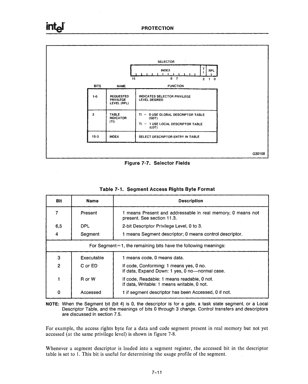
Figure 7-7. Selector Fields
Table 7-1. Segment Access Rights Byte Format
Bit | Name | Description |
7Present1 means Present and addressable in real memory; 0 means not present. See section 11.3.
6,5 | DPL |
4Segment1 means Segment descriptor; 0 means control descriptor. For Segment= 1, the remaining bits have the following meanings:
3 | Executable | 1 means code, 0 means data. |
2 | C or ED | If code, Conforming: 1 means yes, 0 no. |
|
| If data, Expand Down: 1 yes, 0 |
1 | RorW | If code, Readable: 1 means readable, 0 not. |
|
| If data, Writable: 1 means writable, 0 not. |
0 | Accessed | 1 if segment descriptor has been Accessed, 0 if not. |
NOTE: When the Segment bit (bit 4) is 0, the descriptor is for a gate, a task state segment, or a Local Descriptor Table, and the meanings of bits 0 through 3 change. Control transfers and descriptors are discussed in section 7.5.
For example, the access rights byte for a data and code segment present in real memory but not yet accessed (at the same privilege level) is shown in figure
Whenever a segment descriptor is loaded into a segment register, the accessed bit in the descriptor table is set to I. This bit is useful for determining the usage profile of the segment.
