OVERVIEW OF NUMERIC PROCESSING
15
I B I Co I ST I c" I c, IeoJEsl X I PE IUEIOEIZEIDEIIE I
I | EXCEPTION FLAGS (1 ~ EXCEPTION HAS OCCURRED) |
INVALID OPERATION' | |
| DENORMALIZED OPERAND' |
| ZERO DIVIDE' |
| OVERFLOW' |
| UNDERFLOW' |
| PRECISION' |
| (RESERVED) |
| ERROR SUMMARY STATUS(1) |
| CONDITION CODE(2) |
| STACK TOP POINTER(3) |
| NEU BUSY |
(1)ES IS SET IF ANY UNMASKED EXCEPTION BIT IS SET, CLEARED OTHERWISE.
(2)SEE TABLE
(3)ST VALUES
000 ~ REGISTER 0 IS TOP OF STACK
00 1 ~ REGISTER 1 IS TOP OF STACK
111 ~ REGISTER 7 IS TOP OF STACK
'FORDEFINITIONS, SEE THE SECTION ON EXCEPTION HANDLING
G30108
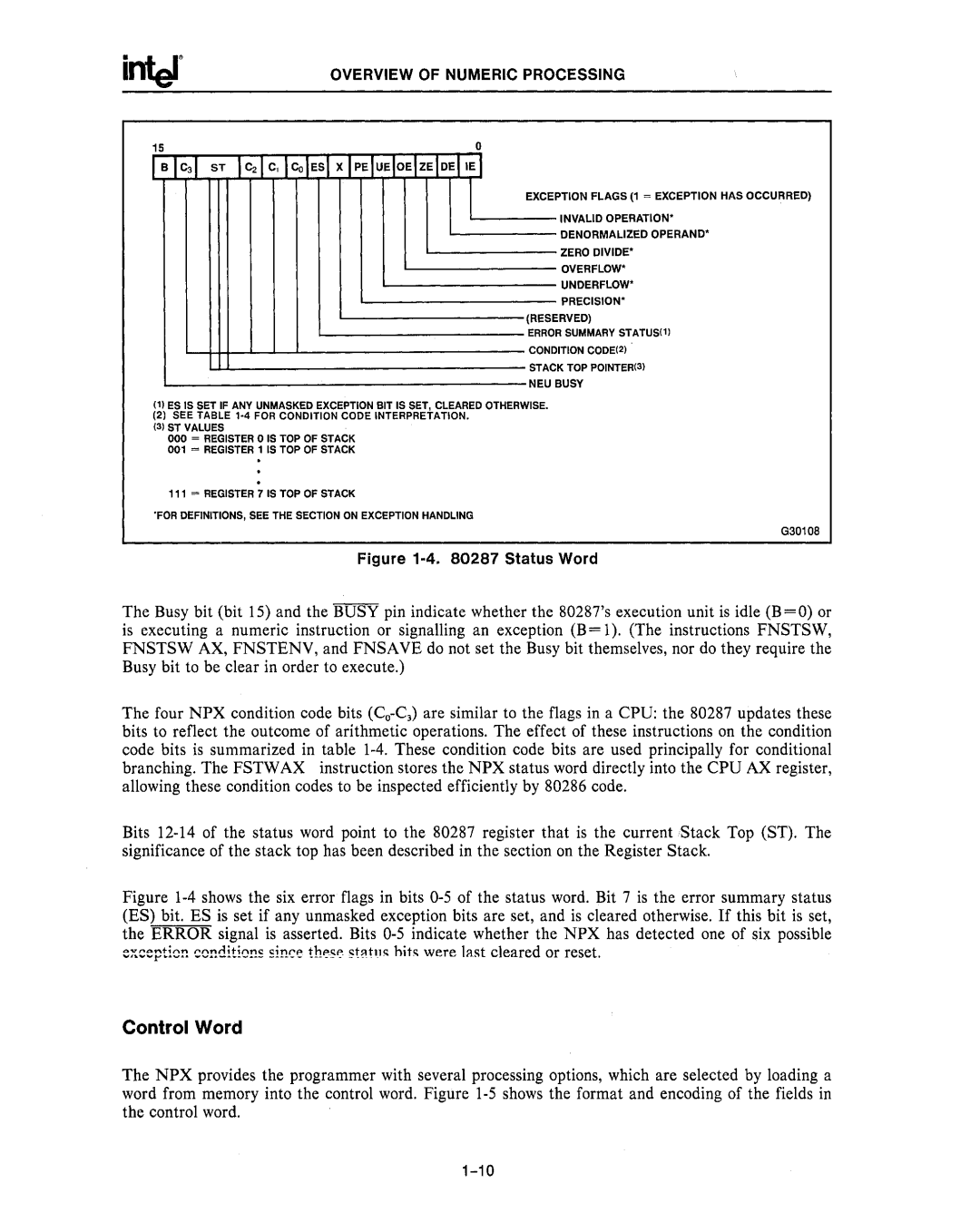
Figure 1-4. 80287 Status Word
The Busy bit (bit 15) and the BUSY pin indicate whether the 80287's execution unit is idle (B=O) or is executing a numeric instruction or signalling an exception (B= 1). (The instructions FNSTSW, FNSTSW AX, FNSTENV, and FNSAVE do not set the Busy bit themselves, nor do they require the Busy bit to be clear in order to execute.)
The four NPX condition code bits
Bits
Figure 1-4 shows the six error flags in bits 0-5 of the status word. Bit 7 is the error summary status (ES) bit. ES is set if any unmasked exception bits are set, and is cleared otherwise. If this bit is set, the ERROR signal is asserted. Bits 0-5 indicate whether the NPX has detected one of six possible
:::i:::::pti~!), c~!),d!t!a!!~ ~im:o:' tho:'5o:' 5t~hl~ hit~ were last cleared or reset.
Control Word
The NPX provides the programmer with several processing options, which are selected by loading a word from memory into the control word. Figure