TABLE OF CONTENTS
Figures
Figure |
| Title |
|
|
| Page |
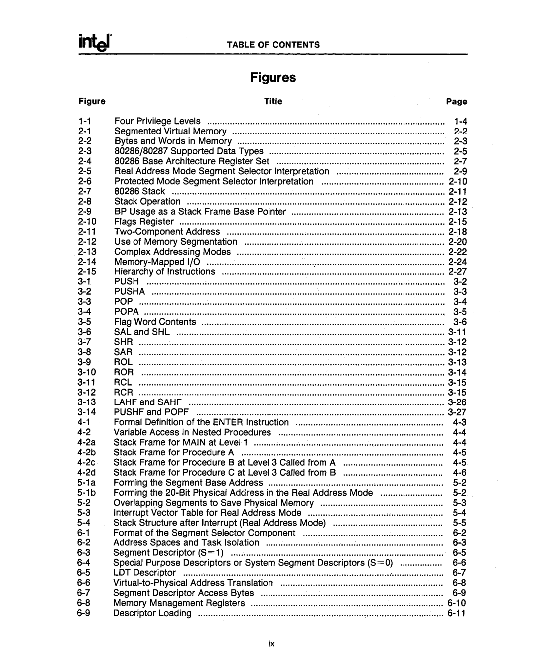
Four Privilege Levels | ....... ..... ................. ........ | .............. .......... | .... .......... | .................... | ||
Segmented Virtual Memory | ||||||
Bytes and Words in Memory |
|
| ||||
80286/80287 Supported Data Types | ||||||
80286 Base Architecture Register Set |
|
| ||||
Real Address Mode Segment Selector Interpretation |
| |||||
Protected Mode Segment Selector Interpretation |
| |||||
80286 Stack |
|
|
| |||
Stack Operation |
|
|
| |||
BP Usage as a Stack Frame Base Pointer |
|
| ||||
Flags Register |
|
|
| |||
|
| |||||
Use of Memory Segmentation | : |
| ||||
Complex Addressing Modes |
|
| ||||
................................................................................................ |
|
| ||||
Hierarchy of Instructions |
|
| ||||
PUSH | : |
|
| |||
PUSHA | ................... | |||||
POP |
|
|
| |||
POPA |
|
|
| |||
Flag Word Contents | ..... ................... | |||||
SAL and SHL |
|
|
| |||
SHR |
|
|
| |||
SAR |
|
|
| |||
ROL |
|
|
| |||
ROR |
|
|
| |||
RCL |
|
|
| |||
RCR |
|
|
| |||
LAHF and SAHF |
|
|
| |||
PUSHF and POPF |
|
|
| |||
Formal Definition of the ENTER Instruction |
|
| ||||
Variable Access in Nested Procedures |
|
| ||||
Stack Frame for MAIN at Level 1 |
|
| ||||
Stack Frame for Procedure A | ||||||
Stack Frame for Procedure B at Level 3 Called from A | : | |||||
Stack Frame for Procedure C at Level 3 Called from B |
| |||||
Forming the Segment Base Address | ||||||
Forming the | ||||||
Overlapping Segments to Save Physical Memory | ................... | |||||
Interrupt Vector Table for Real Address Mode |
| |||||
Stack Structure after Interrupt (Real Address Mode) | :.... | |||||
Format of the Segment Selector Component | ........................................................ |
| ||||
Address Spaces and Task Isolation |
|
| ||||
Segment Descriptor (S = 1) | ||||||
Special Purpose Descriptors or System Segment Descriptors (S=O) | ................. | |||||
LDT Descriptor |
|
|
| |||
Segment Descriptor Access Bytes |
|
| ||||
Memory Management Registers |
|
| ||||
Descriptor Loading |
|
|
| |||
ix
