Intel 80287, 80286 manual Status and Control Registers

Models: 80287 80286

1 515
Download 515 pages 45.04 Kb
Page 40
Image 40

80286 BASE ARCHITECTURE

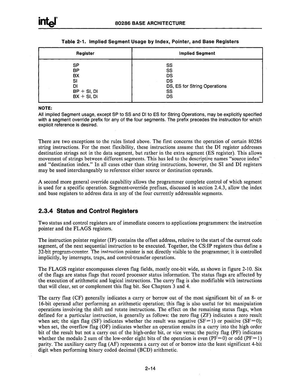
Table 2-1. Implied Segment Usage by Index, Pointer, and Base Registers

Register

Implied Segment

SP

55

BP

SS

BX

OS

SI

OS

01

OS, ES for String Operations

BP + 51, 01

SS

BX + SI, 01

OS

NOTE:

All implied Segment usage, except SP to SS and 01 to ES for String Operations, may be explicitly specified with a segment override prefix for any of the four segments. The prefix precedes the instruction for which explicit reference is desired.

There are two exceptions to the rules listed above. The first concerns the operation of certain 80286 string instructions. For the most flexibility, these instructions assume that the DI register addresses destination strings not in the data segment, but rather in the extra segment (ES register). This allows movement of strings between different segments. This has led to the descriptive names "source index" and "destination index." In all cases other than string instructions, however, the SI and DI registers may be used interchangeably to reference either source or destination operands.

A second more general override capability allows the programmer complete control of which segment is used for a specific operation. Segment-override prefixes, discussed in section 2.4.3, allow the index and base registers to address data in any of the four currently addressable segments.

2.3.4 Status and Control Registers

Two status and control registers are of immediate concern to applications programmers: the instruction pointer and the FLAGS registers.

The instruction pointer register (IP) contains the offset address, relative to the start of the current code segment, of the next sequential instruction to be executed. Together, the CS:IP registers thus define a 32-bit program-counter.The instmction pointer is not directly visible to the programmer; it is controlled implicitly, by interrupts, traps, and control-transfer operations.

The FLAGS register encompasses eleven flag fields, mostly one-bit wide, as shown in figure 2-10. Six of the flags are status flags that record processor status information. The status flags are affected by the execution of arithmetic and logical instructions. The carry flag is also modifiable with instructions that will clear, set or complement this flag bit. See Chapters 3 and 4.

The carry flag (CF) generally indicates a carry or borrow out of the most significant bit of an 8- or 16-bit operand after performing an arithmetic operation; this flag is also useful for bit manipuiation operations involving the shift and rotate instructions. The effect on the remaining status flags, when defined for a particular instruction, is generally as follows: the zero flag (ZF) indicates a zero result when set; the sign flag (SF) indicates whether the result was negative (SF= 1) or positive (SF=O); when set, the overflow flag (OF) indicates whether an operation results in a carry into the high order bit of the result but not a carry out of the high-order bit, or vice versa; the parity flag (PF) indicates whether the modulo 2 sum of the low-order eight bits of the operation is even (PF=O) or odd (PF= 1) parity. The auxiliary carry flag (AF) represents a carry out of or borrow into the least significant 4-bit digit when performing binary coded decimal (BCD) arithmetic.

2-14

Page 40
Image 40
Intel 80287, 80286 manual Status and Control Registers, Implied Segment Usage by Index, Pointer, and Base Registers