Intel 80286, 80287 manual Al,Fe, Out Ff,Al

Models: 80287 80286

1 515
Download 515 pages 45.04 Kb
Page 49
Image 49

80286 BASE ARCHITECTURE

2.5.11/0 Address Space

The 80286 provides a separate I/O address space, distinct from physical memory, to address the input/ output ports that are used for external devices. The I/0 address space consists of 216 (64K) individually addressable 8-bit ports. Any two consecutive 8-bit ports can be treated as a 16-bit port. Thus, the I/0 address space can accommodate up to 64K 8-bit ports or up to 32K 16-bit ports. I/0 port addresses 00F8H to OOFFH are reserved by Intel.

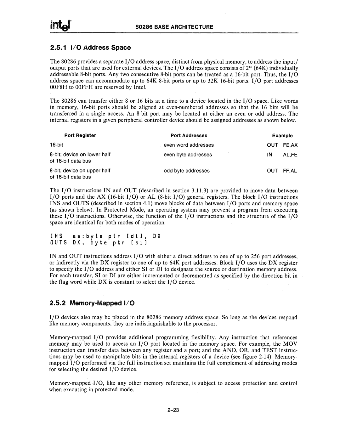
The 80286 can transfer either 8 or 16 bits at a time to a device located in the I/O space. Like words in memory, 16-bit ports should be aligned at even-numbered addresses so that the 16 bits will be transferred in a single access. An 8-bit port may be located at either an even or odd address. The internal registers in a given peripheral controller device should be assigned addresses as shown below.

Port Register

Port Addresses

Example

16-bit

even word addresses

OUT

FE,AX

a-bit; device on lower half

even byte addresses

IN

AL,FE

of 16-bit data bus


a-bit; device on upper half

odd byte addresses

OUT

FF,AL

of 16-bit data bus


The I/0 instructions IN and OUT (described in section 3.11.3) are provided to move data between I/0 ports and the AX (l6-bit I/O) or AL (8-bit I/O) general registers. The block I/O instructions INS and OUTS (described in section 4.1) move blocks of data between I/0 ports and memory space (as shown below). In Protected Mode, an operating system may prevent a program from executing these I/0 instructions. Otherwise, the function of the I/0 instructions and the structure of the I/0 space are identical for both modes of operation.

INS es:byte ptr [dil, DX

OUTS DX, byte ptr [sil

IN and OUT instructions address I/O with either a direct address to one of up to 256 port addresses, or indirectly via the DX register to one of up to 64K port addresses. Block I/0 uses the DX register to specify the I/0 address and either SI or DI to designate the source or destination memory address. For each transfer, SI or DI are either incremented or decremented as specified by the direction bit in the flag word while DX is constant to select the I/0 device.

2.5.2 Memory-Mapped 1/0

I/0 devices also may be placed in the 80286 memory address space. So long as the devices respond like memory components, they are indistinguishable to the processor.

Memory-mapped I/0 provides additional programming flexibility. Any instruction that references memory may be used to access an I/0 port located in the memory space. For example, the MOY instruction can transfer data between any register and a port; and the AND, OR, and TEST instruc- tions may be used to manipulate bits in the internal registers of a device (see figure 2-14). Memory- mapped I/0 performed via the full instruction set maintains the full complement of addressing modes for selecting the desired I/0 device.

Memory-mapped I/O, like any other memory reference, is subject to access protection and control when executing in protected mode.

2-23

Page 49
Image 49
Intel 80286, 80287 manual Al,Fe, Out Ff,Al