Digital Solutions Division
FCC Requirements
Radio Frequency Interference
Important Notice Music-On-Hold
Publication Information
Toshiba America Information SYSTEMS, INC. Tais
Toshiba America Information Systems, Inc
Contents
Strata CTX Configuration
Strata CTX100-S/CTX100 Installation
Iii
Rack Mount Cabinets
PCB Installation
Isdn Interfaces
Vii
IP Telephony and Qsig Over IP
MDF PCB Wiring
11-14
Peripheral Installation
Xii
Introduction
Xiii
Index
Advises you that hardware, software applications, or data
General Description
Programming Manual
User Guides
Quick Reference Guides
Xvi
CTX28 Installation
Inspection
Packaging and Storage
CTX28 FCC/ACTA Registration Numbers
Input Power
Site Requirements
Clearance and Location
Environmental Specifications
Power
Power Converter
Standard Telephone Ring Circuit Gmau and Gstu
AC Power and Grounding Requirements
CTX28 Cabinet
TB2
AC Voltage 90VAC ± 264VAC AC Current Amps max
AC Power Ground Test
To perform the earth ground test procedure
Gmau
Installing the CTX28 Cabinet
Mount the Cabinet on the Wall
To mount the Base KSU
Cover Screws Side Cover
CTX28 Base KSU Interior
PCB Installation
Overview Instructions
PCB Descriptions
CTX28 CHSU28 Cabinet circuit cards Part Title Description
Gcdu CO, CLID, DKT
Set Jumpers on the GMAU1A Motherboard
CTX28 Installation
Install the GVMU1A Voice Mail PCB optional
Jumper Admin PC Real Time Debug Monitor
Busy/Idle On = Busy OFF = Idle
Install the GCTU1A Processor
To install the GCTU1A into the CTX28
Control/Indicator Type of Component Description Connector
Gctu
Install the GCDU1A DKT and Loop Start Interface
To install the GCDU1A
GCDU1A Controls, Indicators and Connectors
GCDU1A PCB
Install the GSTU1A
Install the GETS1A
To install the GETS1A
CD1 LED
Install the BSIS1A optional
Install the HPFB-6 Reserve Power Battery/Charger
12 CTX28 Reserve Power Duration Estimates
Hardware HPFB-6
Install Wiring
14 HPFB-6 Reserve Power Installation
P10 to Hpfb Battery Cord TB1 to Hpfb FG
RS-232C Base TX Music On Hold MOH
16 AC Adapter Wiring Procedure
Digital Telephone Connection
CTX28 KSU or Maximum line length 24 AWG Mode Pair
Battery Backup Feet Meters
Loop Limits
13 Digital Telephone/DIU/DDSS Console/ADM/Loop Limits
Installation
CTX28 Secondary Protection
CTX28
MDF Wiring
14 Station Wiring for Amphenol Connector P1 on GMAU1
Pin No Signal Station
Gvmu Administration PC Connections
Strata CTX28
PPTC-9
PPTC25-MDM
Strata CTX Configuration
Strata CTX100-S/CTX100 Overview
CTX100-S and CTX100 Processors
CTX100 Cabinet Slots
CTX100-S/CTX100 License Control
Licensed Software Options
Strata CTX670 Overview
CTX670 Processor PCBs
Hardware described in this chapter. See
Large-scale Integrated LSI circuits
Network Interface
CTX670 License Control
CTX670 Processor PCB Subassemblies
CTX670 Cabinet Slots
Strata CTX670 Base Cabinet Interior
CTX670 Remote Expansion Cabinet
System Capacities
Cabinet and Slot Capacities
Station/Peripherals System Capacities
Line Capacities and Universal PCB Slots
Base & Expansion
Lines
Station Buttons
Station Buttons per System
System Feature Capacities
Features
CTX100 Base CTX670 CTX670 Expanded Features
Mute External BGM Control Relay4 Zone Relays4
Universal Slot PCBs
Station, Line and Option PCBs
Station PCBs
Digital Telephone Interface Unit BWDKU1A
Digital/Standard Telephone Interface Unit Rdsu
Interface Options
Volt Supply Internal Option R48S
Caller ID Interface Subassembly Rcis
CO Line PCBs Strata Net Over VoIP Interface Unit BIPU-Q1A
Internet Protocol IP Interface Unit Bvpu
Interface Options LAN, Internet, WAN
CO Line PCBs Isdn U-type Basic Rate Interface Unit Rbuu
Isdn Primary Rate Interface Unit BPTU1 or RPTU2
Loop Start CO Line Interface Unit Rcou
T1/DS-1 Interface Unit RDTU2
Functional Block Diagrams
CTX100 System Processor and Option Interface PCBs
BPSU672 Cabinet
CTX100 and CTX670 CO Line Side Functional Block Diagram
CTX100 and CTX670 Station Side Functional Block Diagram
CTX670 Remote Cabinet Configuration Considerations
Worksheet Description
Component Worksheets
Worksheet 1 Toshiba DKT and IP Telephones
Main Location Remote Location 1 2 3 4 5
IP Telephone Qty
Worksheet 2 Standard Telephone, Stratagy DK, IVP8
Main Location Remote Location 1 2 3 45
Miscellaneous Digital Telephone Equipment See Table
Miscellaneous Standard Telephone SLT Equipment Required
Worksheet 3 CO Line
PCB
PCB Name Slots Required Qty
Miscellaneous CO Line Equipment
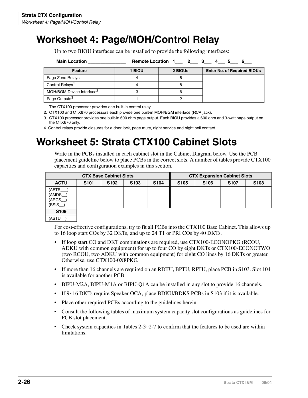
Worksheet 4 Page/MOH/Control Relay
Worksheet 5 Strata CTX100 Cabinet Slots
Actu
Worksheet 5 Strata CTX100 Cabinet Slots
CTX100 Max. Capacity Configuration Examples
Bdku Adku
Bdks
Bdku Rcou RCIU/RCIS Bdks Rcos
Bdku Rcou Bdks Rcos
Bdku Rcou
Bdks Rcos
Bdku Rcou Adku
RCIU/RCIS Adku
Clid
Rcou RCIU/RCIS
CTX100 Base 40 stations and 24 T1 and/or PRI lines
34 CTX100 Base 16 stations and 48 T1 and/or PRI lines
S102 S103 S104
Bdku Bdks
RDTU2 Bdku Bdks
RDTU2 Adku Bdks
Line Ground Start only
Strata CTX Configuration
CTX100 Analog Tie, did and/or Ground Start Lines
Strata CTX Configuration
Worksheet 6 Strata CTX670 Cabinet Slots
PCB Placement Guidelines
52 Main Processor PCB/ Remote Cabinet Configuration
Rrcu PCBs Remote Cabinet Configuration Rrcu PCBs Needed at
Processor PCBs
53 Remote Cabinet Data Cables and Connectors
54 Rdtu PCB Cabinet Slot Configuration
Biou Interface PCB
T1 Digital Line PCBs
55 Bptu or Rptu PCB Cabinet Slot Configuration
Isdn PRI Digital Line PCBs
PRI Lines Slots Bptu or Rptu Bptu or Rptu cabinet slot
Power Factor
Isdn BRI Digital Station PCBs
Analog and VoIP Tie Line PCBs
Isdn BRI Digital Line PCBs
Worksheet 7 System Power Factor Check
+5VDC PF
58 PCB and Power Supply Power Factors PCB Type
+5VDC PF 24VDC PF
Telephone/Device Power Factors
Total Power Factor PF
Main Location Remote Location 4 5
Cabinet Power Factor Check
CTX100
CTX670
CTX670 Cabinet 1 base Slot
Total Cabinet PF CTX670 Cabinet Slot
24VDC PF
Worksheet 8 CTX Primary AC and Reserve Power
CTX100 AC Power Considerations
CTX670 AC Power Considerations
59 Strata CTX100 Electrical Characteristics
Reserve Power CTX100 and CTX670
62 CTX100 Typical Reserve Power Duration Estimates
CTX670 Cabinet Power Enter the Number Components Required
Number of Cabinets
Primary/Reserve Power Cabinet Hardware
APSU112
ABTC-3M
Abcs
BPSU672
RPSB2
BPSB240
BACL240
Bbdb
Local Electrical Code Cabinet Cabinets
Local Electrical Cabinet Cabinets
Cabinet AC Power Component Installation
Local
Cabinet Cabinets
Local Cabinet
Worksheet 9 Software Licenses
Part Number Strata CTX Comments Qty Software Licenses
Hardware Compatibility
71 Hardware Compatibility
Admin Modem
Power Supply Unit
Battery Distribution
Power Strip
Strata CTX100-S/CTX100 Installation
CTX100 Installation Strata CTX100-S
Cabinet Size and Weight
Side View
Power Considerations
Environmental Considerations
BTU Rating Base plus Expansion Cabinet
AC Power and Third-wire Ground Test
Alternate or Additional Ground
Installing the CTX100 Cabinet
Remove Cabinet Covers
Remove the Back Cover from the Cabinets
Cabinet Cover
Check the Base/Expansion Power Supply Jumper Plug
Mount the Base Cabinet
Base
Mount the Expansion Cabinet if required
Install Reserve Power
Base and Expansion Cabinet Interior
Reserve Battery Considerations
Install the Optional ABCS1A Battery Charger
Install the Battery Cable
Batteries/1-Cabinet Batteries/2-Cabinets
10 Cable Wiring for the Base and Expansion Cabinets Top view
12 Cable Wiring for the Base with an Expansion Cabinet
Check Power Supply Circuit Breakers and Fuses
Check the AC Power Fuses
Check the -24 Volt Circuit Breakers
Check the Power Factor Indicator and Reset Button
14 Power Supply Connectors Top View
Remove and Replace the Power Supply if required
15 Power Supply APSU112
Replacing the Power Supply
Set Jumpers and Install Option PCBs onto the Actu
To install the ACTU2A
To Install ACTU1A
18 Actu PCB CTX100 Processor
Install the Main Processor Actu PCB
Install Other PCBs into the Cabinets
Provides Comments Installs On
CTX100 Cabinet and Processor Components
Actu
Attach and Route PCB Cables
Bsis
SMDR, Smdi
Abcs
22 Avoid Improper Cable Routing
Strata CTX670 Installation
Strata CTX670
Strata CTX670 Installation
Installation Strata CTX670
CTX670 Minimum Clearance Requirements
Power Considerations
Reserve Power
FCC Registration Information
Location of Approval Labels
Cabinet Installation Considerations
Recommended Installation Sequence
Step Reference Information
Reset Circuit Breaker
Check the -24 Volt Circuit Breakers
Circuit Breaker Location and Slot Assignments see Figure
Check the Power Factor Indicator and Reset Button
Power Supply BPSU672 Removal
Power Supply Replacement
Power Factor PF alarm LED indicates
Mount Cabinets
Wall Mounting the Base Top Cabinet
Wall Mounting Expansion Cabinets
Cabinet Mounting Surface Diagram
Cabinet Cover Removal and Installation
Marking Hole Trace Upper Arch Back Cover
Hanger Back Cover Hanger Hole Mounting Strip
CTX670 Cabinet Interior
Base Cabinet
Cable Shield
B50MT
Pair Amphenol Cables Knock Out Plastic Top
Pair To MDFAmphenol Cables
Ground the System
11 Cabinet Grounding
Install AC Power Components
AC Power Requirements
Cabinet AC Power Component Description
Power Cabinet Hardware Option Description
AC/Reserve Power and Data Cabling Overview
BBTC2A-2M battery cables supplied with Bbdb Power Supply
Power Strip Cables
BBTC1A-2M Cables To Reserve Power Batteries 2 m
13 208VAC/240VAC Power/Data Cabling for up to Seven Cabinets
Cabinet AC Power Considerations
Local Electrical Code Cabinets
Local Cabinets
14 AC Power Strip Installation
15 AC Power Cords for One to Five Cabinets
16 AC Power Cords in Six or Seven Cabinets
Right Side AC Power Cables Front
RPSB2 or BPSB240 Power Strip
To AC Outlet
Bonding Connection Plates
Install Reserve Power
Typical Reserve Power Duration Estimate Number of Cabinets
Reserve Battery Cabinet Components/Cables
Reserve Power for One or Two Cabinets Wall Mount
Bbdb
Reserve Power for Three or More Cabinets Wall Mount
Batteries/1~7 Cabinets with Bbdb
Cabinet Floor Mounting
Floor Mounting One or Two Cabinets
BCCB240
Bfif
Floor Mounting Three or More Cabinets
Mounting Screws Anchor Bolts Bfif is inside of cabinet edge
Anchor Bolts
Floor Fixture Bfif
Mounting Screws
Bolt Cabinets to Concrete Floor
Drilled holes
Bolt Cabinets to Wooden Floor
Bolt Cabinets to Computer Room Floor
Strata CTX670 Installation
Three or more BCCB120 Cabinets Bfif
Strata
Battery Wire Specifications #10 AWG minimum 2 pairs 42A max
Batt Bccb
Conduit Holes to 1/2 inch trade size From
20A dedicated
Strata CTX670 Installation
PCB Installation Considerations
PCB Option Considerations
Hardware Options
Software Options
BCTU1A/BEXU1A Installation
P601
Strata CTX670 Installation
Bexu
RJ45 LAN
P601 Batt
LINK, TX, RX LED
P901 Batt
BEXU1A
BECU/BBCU Installation
To adjust the CTX670 MOH/BGM source
31 Bbcu Processor PCB
33 Installing Bexs onto Becu
Base Cabinet see Figure
12 Bbcu Controls, Indicators, and Interface Connectors
Control/Indicator/Connector Type of Component Description
Bexs
Batt
Remote Expansion Cabinet Unit
38 Remote Expansion Cabinet Connection
Remote Cabinet Installation Instructions
39 Remove/Replace Remote Cabinet Cover
Close the data cable doors
RRCU1A
42 ROMS1A Subassembly 15 Fiber Optic Specification
Specification
Status Indicators
BIT
LED
Monitor Port Communication Parameters
Monitor Port Pin Assignments
Strata CTX670 Installation
Basic Specifications
Space
Ventilation
Environmental Conditions
Location
Rack Mount Cabinets
Model BRPSU672AE135386
Assemble Rack
Move Flange Position Optional
Take Off Front and Back Covers
Take Off Base of Cabinet
Attach Cabinet to Rack
Rack Hole Positions
Install and Attach Cabinets to Rack
Reattach Cabinet to Base
Attach Amphenol Cable
Attach the AC Cable
Connect Data and Ground Cables
Verify Power Supply Settings
Install Power Strip BRPSB120A
Optional Install Reserve Power
PBTC1A-3M
BBDB1A
Install Reserve Power for One or Two Cabinets
Install Reserve Power for Three or More Cabinets
Install Reserve Power Battery Distribution Box if required
Rack Mount
Attach Front and Back Covers
Rack Mount Cabinet Grounding
Wiring for 7 Cabinet Configuration
Bottom Up Configuration Center back wiring
Top Down Configuration Back View
Front View Side View
Top Down Configuration Left Front wiring
Primary Power Cabinet Hardware
BRPSB120A
BRPSB240A
BACL240A
Front View
Front View Back View
Cabinet AC Power Considerations
AC Power Component Requirements
Power Supply Unit BRPSU672A
DC Voltage Connector Plug Pin Wires Yellow Blue White Green
Red
Circuit Breaker Location and Slot Assignments
Changing Plug for Power Strip BRPSB240A
Remove Nema 6-20P from Power Strip
Attach Nema L6-20P Plug to Power Strip
Rack Mount Cabinets
AC Cabling
14 AC Cabling One to Five Cabinets
15 AC Cabling Six to Seven Cabinets
Rrcu
Remote Cabinet Data Cables and Connectors
PCB Installation
PCB Chapter Layout
PCB Installation Power Supply Considerations
PCB Hardware/Software Options
CTX100 Actu Processor PCBs
CTX670 BCTU/BEXU Processor PCBs
Adku Installation
Adku Digital Telephone Interface Unit
Adku Hardware Options
Astu Installation
ASTU1 Wiring
Astu Standard Telephone Interface Unit CTX100 only
Astu Electrical Characteristics Description
SW2
FG1
Wire from Astu P2 plugs into Actu P8
Bdku Installation
To install the Bdks
BDKU/BDKS Digital Telephone Interface Unit
Bdku Hardware Options
Bdku Controls, Indicators, and Interface Connectors
BDKU/BDKS PCB
Biou Installation
Biou Option Interface Units
MOH1, MOH2, MOH3
N.O
R48S -48 Volt Supply Subassembly Installation
BSTU/RSTU Installation
BSTU/RSTU Standard Telephone Interface Unit
RSTU1, 2 and 3 Controls, Indicators, and Connectors
Bstu Controls and Interface Connectors
RSTU3 Controls and Interface Connectors PCB Installation
Rstu or RSTU2 Controls and Interface Connectors
Bvpu Configuration
Bvpu Installation
Bvpu Internet Protocol IP Interface Unit
SW0
11 Bvpu PCB
BWDKU1A Installation
BWDKU1A Digital Telephone Interface Unit
BWDKU1A and BDKU/BDKS Comparison
BWDKU1A BDKU/BDKS
PDKU2 Installation
PDKU2 Digital Telephone Interface Unit
PDKU2 Hardware Options
RCIU1/RCIS or RCIU2/RCIS Installation
RCIU1 or RCIU2 Installation
RCIU1, RCIU2, Rcis Caller ID Interface
14 RCIU1/RCIS PCB
Rcos Installation Internal Option
To install an RCOS3A PCB
Lights to indicate that line circuit is in operation
16 RCOS3A PCB
Rcou Installation
To install an RCOU3A or RCOU1A PCB
18 RCOU3A PCB
20 PCOU2 PCB
Rddu Installation
Rddu Direct Inward Dialing Line Interface Unit
Rddu
Installing R48S Ring Generator Internal Option
Installing Rsts Internal Option
Rdsu Installation
To install the R48S on the Rdsu
22 RDSU, Rsts PCBs PCB Installation
REMU2A and Remu Installation
Pemu Installation
RDTU2 T1 Interface Unit
REMU2A Tie Line Unit
REMU2A Tie Line Unit
24 Remu PCB
25 Pemu PCB PCB Installation
RGLU2 Installation
To install an RGLU2 PCB
RGLU2 Loop/Ground Start CO Line Interface Unit
PCB Installation
Rcms Subassemblies Installation
RMCU/RCMS E911 Cama Trunk Direct Interface
Rmcu Installation
28 Rcms Subassembly stand-alone
29 Rmcu Interface Card
Rcms LEDs
20 LED Indications Normal Operation Status
NB LED CB LED
Network Busy Customer Busy
Network Requirements
21 PCB Network Requirements
PCB/Interface Facility Interface Code Network Jack Ringer
PRI Overview
BRI S/T Overview
BRI U Overview
Isdn Interfaces
Strata CTX Isdn Reference Model
Isdn Reference Model
BPTU/RPTU Overview
CSU Requirements
Slot Assignments
Bptu Installation
Power Factor
To install an Bptu PCB
Bptu Interface Unit
BPTU1A
Bptu Cable Length Equalizer Switches
Bptu Self Test
SW4 SW5 SW6
Bptu Front Panel Indicators
Bptu Loop Back Jumper Plugs
Ferrite Core
Bptu Cabling
Rptu Installation
To install an Rptu PCB
Rptu Switches, Jumpers, and Connectors
Switches/Jumpers/Connector Description
Isdn
Interfaces
Rptu SW1 Cable Length Settings
Rptu LED Functions
Functions
SW1
Bptu and Rptu Cabling
Cable Length
Cable Installation
Fifteen feet of CAT5 unshielded cable
Ferrite Core Installation
Ferrite Core
RBSU/RBSS Interface Units
Overview
Rbsu Connection Options
Capacity and Cabinet Slot Information
RBSU/RBSS Interfaces between the S/T Reference Points
PS-1 Backup Power Option
RBSU/RBSS Installation
Set Option Switches/Jumpers
Run Related Programs
RBSU/RBSS Option Switches, Jumpers, and Connectors
Circuit Option Type Circuit Type Description Switch
Install the Rebs
Install the Rbss
Install the R40S
Modular Jack Pin Configurations
Install RBSU/RBSS PCBs into Cabinet
BRI S/T Circuit Jack TE or NT Mode
Monitor Jack
CKT1 CKT3
RBSU/RBSS Premise Wiring Guidelines
Power Failure Terminal Screws
BRI Wire Type Recommendations
RBSU/RBSS BRI Cable Jacks and Connectors
RX+
TX+
Connecting Rbsu to Network Side TE-Mode
Strata CTX BRI Circuit EMC Ferrite Core Requirement
Connecting RBSU/RBSS Station Devices NT-Mode
17 Rbsu to NT1 Point-to-point Connection
18 RBSU/RBSS NT Circuit Pinout on Passive Bus
RBSU/RBSS Passive Bus Configurations
19 Simplified Short-branched Passive Bus
Rbuu Installation
To install the subassemblies Rbus
To install an Rbuu PCB
RBUU/RBUS Interface Unit
23 Rbuu PCB
Definition LED Off LED On LED Blinking
PSI1
RBUU/RBUS Wiring Guidelines
Line-side cabling
RJ45 Jack
Isdn Interfaces RJ11 Demarc Jack
RJ45 Demarc Jack
Station-Side Cabling
Call Monitor Jack Cabling
Isdn Testing and Troubleshooting
BRI-U, LT Interface Terminal Loop Back Test
Strata System
Loop-back Test
30 Loop-back Test
Timing and Synchronization
Loop-back Test
31 Primary and Secondary References
PRI/BRI Call Monitoring
Call Monitor Output for Isdn
33 PRI Start-up and Synchronization Sequences
34 PRI Outgoing Call Connect and Release
35 Outgoing Call Setup Output of BRI Call Monitor
BRI Call Monitor
36 Incoming Call Setup Output of BRI Call Monitor
Isdn Interfaces
Program Channels
Select Slot Assignments
RDTU3 T1 Interface Unit
RDTU3 PCB
RDTU3 LED Functions RDTU3 LEDs Indication
Rdtu Installation
To install an Rdtu PCB
RDTU3 Cabling
RDTU3 to Network
RDTU3 to PBX T1 Separated More Than 655 ft
Rdtu to PBX T1 Direct Back-to-back Connection up to 655 ft
Network Jack/RDTU3 Modular Jack Pin Function
Connecting two RDTU3 PCBs
RDTU3 Self Test and CSU Test Switch
RDTU3 Equalizer Switches
RDTU3 Front Panel Indicators
RDTU3 Loop Back Jumper Plugs
Call Data Monitor Jack
Loop Back
Commands
RDTU3 Status Commands Function Format Indication
RDTU3A Call Data Information
Indicators
ALARMYAON/OFF BAON/OFF FSLON/OFF
RDTU3 Indications Timing Type
DT DHin Data Code Data Hex Meaning
DT DHin Data Code Data Hex Meaning
10 DR DHout Data Code Data Hex Meaning
SW1 Equalizer Switch and Loop Back Jumpers Internal Option
RDTU1 & 2 Installation
RDTU1 & 2 T1 Interface Unit
CTX
RDTU1A
12 RDTU1 and 2 LED Functions Alarm LED
Falm
Mfalm
Yalm
RDTU1 and 2 Cable Installation
Rdtu Cable Connections
CSU Installation
Loop Back Testing
Rdtu Self Test
Network/CSU T1 Span Test
Network/CSU/RDTU Span Test
Test Rdtu Lines
Loop Back Testing
Pre-installation Guidelines
IP Telephony and Qsig Over IP
Dos and Don’ts for Setting Up the System
Client Firewall Considerations
Perform a LAN Voice Readiness Assessment
Methods of Estimating Bandwidth Requirements
CTX
Review Voice Quality Considerations
Prgs
Above and the Codec parameters
711 at 20ms
Install BIPU-M2A
Connect BIPU-M2A to LAN or VPN Server
Indicator Definition
BIPU-M2A Interface Unit
BIPU-M2A or BIPU-Q1A Buttons, LEDs and Jumpers
Install IP Telephones
IPT Operation Notes
Over IP IP Telephony
Qsig
Tilt Stand Installation
IPT Telephone Options
IP Telephone Add-on Modules
External Speaker Unit Hesb Option
Handset/Headset Option Straps
Station Option Interface PCB Compatibility
Strap on IPT PCB Explanation
To wall mount IP telephones
Handset Hanger
Connect IPTs to Network
IPT Connections
IPT Anywhere
IP Telephony and Qsig Over IP
Security Requirements
IP-CTX Virtual Private Network Connections Example
Power over LAN
Addressing
CAT5
OUT
OUT CAT5
IPT
Installing and Operating the SoftIPT
Hardware/Software Required
Before You Begin
Install SoftIPT
Upgrading the SoftIPT
Start the SoftIPT
Switching a Call to Your Headset
Making a Call
To make a call
Using the Directory to Call
Creating a Directory
Labeling Feature Buttons
To change Feature Button Labels
Using the Call Log
Uninstalling the SoftIPT
To access the Call Log
To remove SoftIPT from your PC
Application Notes for Wireless 802.11 Networks
Wireless Recommendations
Considerations
Tested Platforms
Audio Devices
PC Platforms
CTX IP Troubleshooting
IP Telephone Ping Test
7Ping Test Action LCD Indication Remarks
Ping to
LCD Network Failure Displays
Collect CTX Trace Data on CTX SmartMedia Card
Collect Bipu Logs
8LCD Network Failure Conditions LCD Indication Remarks
Check Log0.log/Log0.err for Error Message Output
Bipu Reset
CTX System Configuration
Optional Data for Program Update
Verify CTX/BIPU/IPT Hardware, Software and Firmware Version
Mandatory Data
Network Diagram
Network Information
Network Equipment that BIPU/IPT Directly Connects To
CTX100 Slot Base Exp
Capture Packets
Protocol Name Type Use, Purpose
How To Capture Packets
Using Repeater Hub Dumb Hub
Using Switching Hub with Mirroring Function
Capture Points
IP Troubleshooting Resolutions
Using PC or Workstation With Multiple Network Interfaces
10 IP Troubleshooting Problems and Resolutions
Problem Action Cause How to Resolve
LAN Problems
Problem Action Cause How to Resolve IPT Problems
Connect Error
Private Networking Over Internet Protocol
BIPU-Q1A Strata Net Qsig over IP Interface Unit
12 Qsig over IPClass Definitions Delay ms Jitter ms
Strata Net Qsig Over IP and IPT Bandwidth Requirements
Class
Kbps
BIPU-Q1A Installation
Connect BIPU-Q1A to LAN, Server or Router
10-1
MDF
Mode Pair Pair plus
Station Loop Lengths
10-2
Station Loop Lengths1
MDF PCB Wiring
10-3
Loop Limits for DKT3000-series Telephones
Station Wiring Diagrams
10-4
Adku and BDKU/BDKS Digital Station Wiring
10-5
Bwdku Digital Station Wiring
10-6
Astu Wiring
10-7
Pdku Digital Station Wiring
Pdku Wiring
Digital Telephone DSS and Ddcb External Power Connection
10-9
MDF PCB
10-10
Bdku Station MDF Cross Connect Record
KSU Slot Number
Adku Bdku Pdku Bdks
Rdsu Wiring
10-11
10-12
CKT
Port Directory Device/Standard Telephone Location Number
Rstu or Pstu Analog Devices Wiring
10-13
10-14
Port Intercom Device/Standard Telephone Location Number
Power Failure Cut Through Dpft Wiring Pin-outs
10-15
10-16
RGLU2, Rcou or Pcou Wiring
10-17
10-18
RCOU/RCOS Wiring
Wiring
10-19
RMCU/RMCS Wiring Diagram
10-20
RCIU1/RCIS or RCIU2/RCIS Wiring
10-21
Did and Tie Line Wiring
10-22
10-23
Lead PIN #
4WR1 2 4WT1
Line #4 Line #3 Line #2
Pemu Wiring
10-24
17 MDF Wiring/4-Wire Tie Line to Pemu
10-25
Option Interface PCB Wiring Diagram
10-26
Series Digital Telephones Telephone
11-1
Station Apparatus
Series Telephone Installation
Digital Telephone System Connection
11-2
3000 Telephone Subassembly Upgrades
Subassembly No. per Function Phone
Series Telephone Option PCBs
11-3
11-4
Bpci Bheu Bvsu ADM Hheu BHEU/HHEU
DKT3000 and DKT2000 Component Compatibility Series DKT
CTI
Telephone Speaker Off-hook Call Announce Upgrade Bvsu
Bvsu Upgrade Installation for DKT3000-series Telephones
11-5
Bvsu Installation
Removing Telephone Base
Telephone Headset Bheu Upgrade
Bheu Installation
11-7
Bheu Installation
11-8
Connector Locations
Telephone Option Straps
11-9
DKT3020-SD
DKT3001 Bheu Connector Location
11-10
Bpci Installation
11-11
Install Tapi Service Provider
11-12
Add/Edit TSP Configuration Information
Test/Use Tapi Service Provider
IPT Telephone
11-13
Series, IPT1020-SD Button Layouts
11-14
11-15
13 DKT3014-SDL Buttons
11-16
14 DKT3001 Buttons
Telephone Settings
Series/IPT Telephones
11-17
Speakerphone/Microphone Sensitivity Adjustment
Reset LCD Contrast for the DKT3014-SDL
11-18
DKT2000 Mode On/Off
Turn DKT2000 Mode On/Off
Msg/Feature Button Activation/Deactivation DKT3001 only
Series Telephones
Country Settings On/Off
Country Code Settings for Mu Law/A Law
11-20
Test the Display on Large LCD Telephones DKT3014-SDL only
Digital Add-on Module Installation
To install DADMs
11-21
Dadm Comparison Add-on Module DADM3020 DADM3120
11-22
15 Digital Add-On-Module
Tilt Stands
11-23
Tilt Stand Installation with Add-on Modules
11-24
21 Release Adjustment Button Station Apparatus
11-25
Tilt Stand for DKT/IPT + Two ADMs
11-26
Telephone Wall Mounting
11-27
To mount digital telephones
11-28
To wall mount DKT3001 or DKT2001 digital SLTs
Direct Station Selection DSS Console/System Connection
Standard Telephones
DSS Console Connections
11-29
Cordless Digital Telephones
11-30
Cordless Telephone Compatibility
Bdks D2
Cordless Telephone Installation
Review Safety Instructions
11-31
11-32
Select Location
Place DKT3000-series Telephones into 2000-Mode
11-33
To change DKT3000-series telephones into 2000-mode
Connect Telephone Cables
11-34
To connect as a stand-alone telephone
To connect to a Strata DKT
Connect and Apply Power
11-35
Base Unit
Charging Unit
Wall Installation Optional
11-36
Standard Wall Plate Mounting
11-37
Direct Wall Mounting
To wall mount the base unit
11-38
Charging Unit Wall Mounting
Install Handset Battery Pack
Raise the Base Unit Antenna
Charge Batteries for First Time
11-39
Install Headset Optional
Attach Belt Clip Optional
11-40
To remove the belt clip
Cordless Telephone Troubleshooting and Specifications
Troubleshooting
Troubleshooting Suggestions Condition
11-41
Low Battery
Cleaning Charging Unit Contacts
11-42
DKT2204-CT Charging Unit pictured
Charging Spare Battery Packs DKT2204-CT only
Simultaneous Conversation Channels
DKT2204-CT
DKT2304-CT
Telephone Line Problems
Range and Performance
Radio Interference
Privacy
Specifications
Specifications Feature DKT2204-CT DKT2304-CT General
11-45
Base Unit
Telephone Speaker Off-hook Call Announce Upgrade DVSU/ Bvsu
2000 Telephone Subassembly Upgrades No. per Function Phone
Series Telephones
Series Telephone Option PCBs
30 Speaker Off-hook Call Announce Upgrade BVSU1A
31 BVSU/DVSU Installation Station Apparatus
Hheu Installation
11-48
Feed Through To Hesb For HESC-65A Cable Block
SW601 HESC-65 Cable HESC-65A Cable
Locations DKT2020-SD Strap and Connector
11-49
Carbon Headset/Handset Straps
Beep Strap
11-50
External Power Straps
11-51
DIP Switches
10 DKT International DIP Switch Settings
11-52
DIP Switches
11-53
11 DKT2020-FDSP DIP Switch Settings
11-54
To use the External Microphone
11-55
37 Rfdm Plug on DKT2020-FDSP
Speech Training Mode
11-56
Special Button Operation Button
To toggle full/half-duplex mode
DKT 2001 Installation
Digital Single Line Telephone DKT2001 only
11-57
11-58
Peripheral Installation
Application PC and Server Interfaces
12-1
Network Interface Connections
12-2
Network Jack LED Indications
Network Interface Connections Peripheral Installation
12-3
12-4
Application PC or Server Direct Connection
TIA Network Wall Jack Wire Color Codes
12-5
12-6
CTX Modem Programs and Dialing Numbers
12-7
PPTC-25F
Pptc
DTE
Music-On-Hold/Background Music Interfaces
12-8
12-9
MOH/BGM Interface Connection
External Page with Biou Interface
12-10
12-11
Biou 1 or
12-12
12 Zone Page with Multiple Amplifiers
Control Relays with Biou Interface
12-13
Door Phone Wire Connections
Ddcb and Mdfb Cabling
Ddcb Wall Mounting
12-14
Calling from a Door Phone
Calling a Door Phone
Door Lock Control
Door Phone/Lock Programming
16 DDCB3 Wiring and Ddcu Door Lock PCB
12-16
Set Up the Telephone for the External Ringer Option
To Turn the Loud Ringing Bell Feature On/Off Default is Off
External Speaker Unit Hesb Options
Telephone External Ringer
HESC-65A and Bheu Installation
Modular connector SW601 HESC-65 Cable HESC-65A Cable
Telephone Bheu to External Speaker Hesb Cable Connection
12-18
Strap and Connector Locations Installation
12-19
Peripheral
21 Wiring the Telephone External Ringer with Hesb Interface
12-20
To install the Hesb amplified speaker option
Amplified Page Speaker Option
12-21
Test the Telephone External Ringer Option
12-22
To test the amplified speaker option
To install the Hesb amplified page speaker with talkback
Talkback Amplified Page Speaker with Talkback Option
12-23
To test the talkback amplified speaker
Hesb Wall Mounting
12-24
To wall mount the Hesb
One Wall Mounting Hole
Power Failure Options
Power Failure Transfer Unit
12-25
Power Failure Emergency Transfer Dpft Installation
12-26
To test the operation of the Dpft
Station Message Detail Recording Smdr
Smdr Record Types
12-27
Call Record Types
12-28
Smdr Record Format Line Column Name
12-29
Sample Call Record Explanation Rel .02 or lower Field
12-30
Record Formats Release
Smdr Record Format Software Release Line Column Name
12-31
Sample Call Record Explanation Software Release R1.03 Field
12-32
IN-1
Index
IN-2
IN-3
Dtmf
IN-4
QSIG, 2-10,2-17,2-56,7-9
IN-5
IN-6
IN-7
RSTU/PSTU/RSTU2