Input/Output Connectors
Input/Output Connectors
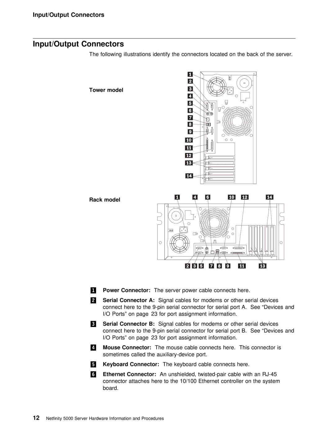
The following illustrations identify the connectors located on the back o
Tower model
Rack model
.1/ | Power | Connector: |
|
| The server power cable connects here. | |||||
.2/ | Serial | Connector | A: |
| Signal | cables | for | modems or other serial devices | ||
| connect | here |
| to the | connector for serial port A. See | |||||
| I/O | Ports” | on | page 23 | for port assignment information. | |||||
.3/ | Serial | Connector | B: |
| Signal | cables | for | modems or other serial devices | ||
| connect | here |
| to the | connector for serial port B. See | |||||
| I/O | Ports” | on | page 23 | for | port | assignment information. | |||
.4/ Mouse Connector: The mouse cable connects here. This connector is sometimes called the
.5/ | Keyboard | Connector: | The keyboard cable connects here. |
|
.6/ | Ethernet | Connector: | An unshielded, | |
| connector attaches here to the 10/100 Ethernet controller | on the sy | ||
| board. |
|
| |
12 Netfinity 5000 Server Hardware Information and Procedures