System Board Switches
System Board Switches
The following table provides the system switch identifiers and descript
switches. The system switch block is identified.3/ in thebyillustrationkey at “System Board Connectors” on page 169.
Note: Turn off the server and disconnect the power cord before moving switches.
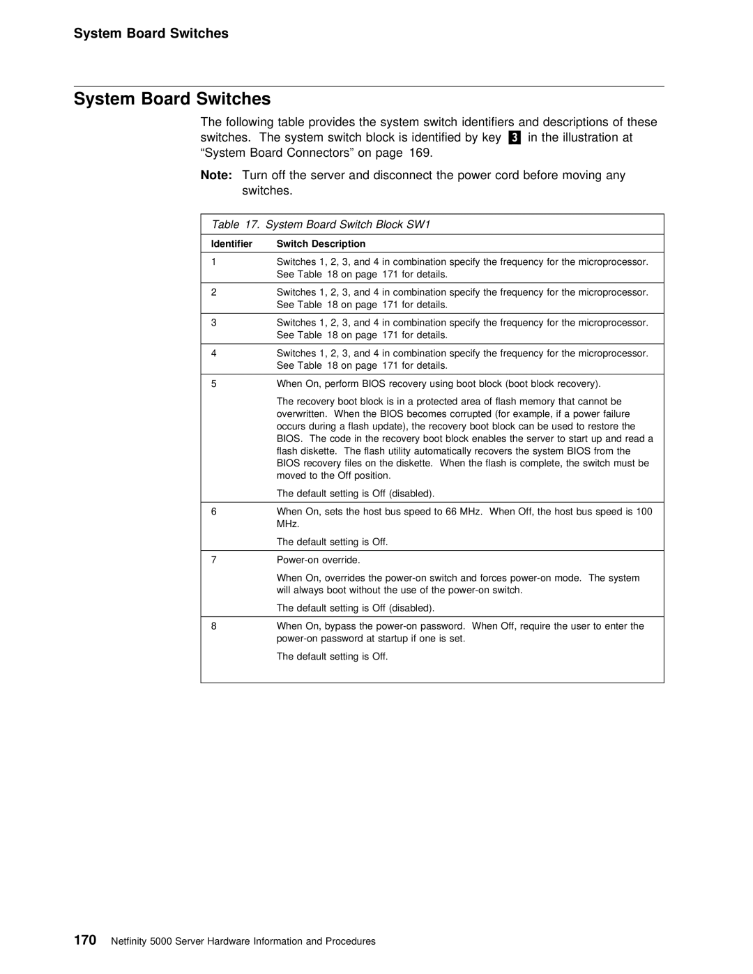
Table | 17. System Board Switch Block SW1 |
|
|
|
|
|
|
|
|
|
|
|
|
|
|
|
|
| |||||||||
Identifier | Switch | Description |
|
|
|
|
|
|
|
|
|
|
|
|
|
|
|
|
|
|
|
|
|
|
|
| |
|
|
|
|
|
|
|
|
|
|
| |||||||||||||||||
1 | Switches | 1, | 2, |
| 3, | and | 4 | in | combination specify the frequency for the micr | ||||||||||||||||||
| See | Table 18 | on |
| page 171 |
| for | details. |
|
|
|
|
|
|
|
|
|
|
|
|
|
|
| ||||
|
|
|
|
|
|
|
|
|
|
| |||||||||||||||||
2 | Switches | 1, | 2, |
| 3, | and | 4 | in | combination specify the frequency for the micr | ||||||||||||||||||
| See | Table 18 | on |
| page 171 |
| for | details. |
|
|
|
|
|
|
|
|
|
|
|
|
|
|
| ||||
|
|
|
|
|
|
|
|
|
|
| |||||||||||||||||
3 | Switches | 1, | 2, |
| 3, | and | 4 | in | combination specify the frequency for the micr | ||||||||||||||||||
| See | Table 18 | on |
| page 171 |
| for | details. |
|
|
|
|
|
|
|
|
|
|
|
|
|
|
| ||||
|
|
|
|
|
|
|
|
|
|
| |||||||||||||||||
4 | Switches | 1, | 2, |
| 3, | and | 4 | in | combination specify the frequency for the micr | ||||||||||||||||||
| See | Table 18 | on |
| page 171 |
| for | details. |
|
|
|
|
|
|
|
|
|
|
|
|
|
|
| ||||
|
|
|
|
|
|
|
|
|
|
|
|
|
|
| |||||||||||||
5 | When | On, | perform | BIOS | recovery using | boot | block | (boot | block |
| recovery). |
|
| ||||||||||||||
| The recovery boot block is in a protected area of flash memory that canno | ||||||||||||||||||||||||||
| overwritten. When the BIOS becomes corrupted (for | example, | if | a | power |
| fai | ||||||||||||||||||||
| occurs during a flash update), the recovery | boot | block | can | be | used | to | re | |||||||||||||||||||
| BIOS. The code in the recovery boot | block | enables | the | server | to | start | up | |||||||||||||||||||
| flash diskette. The flash utility automatically | recovers | the | system | BIOS |
| from | ||||||||||||||||||||
| BIOS | recovery | files | on | the | diskette. When | the | flash | is | complete, | the | switc | |||||||||||||||
| moved | to | the | Off | position. |
|
|
|
|
|
|
|
|
|
|
|
|
|
|
|
|
| |||||
| The | default | setting | is | Off | (disabled). |
|
|
|
|
|
|
|
|
|
|
|
|
|
| |||||||
|
|
|
|
|
|
|
|
|
|
|
|
|
|
|
| ||||||||||||
6 | When | On, | sets | the | host | bus | speed | to | 66 MHz. When | Off, | the |
| host | bus | spee | ||||||||||||
| MHz. |
|
|
|
|
|
|
|
|
|
|
|
|
|
|
|
|
|
|
|
|
|
|
|
|
|
|
| The | default | setting | is | Off. |
|
|
|
|
|
|
|
|
|
|
|
|
|
|
|
|
| |||||
|
|
|
|
|
|
|
|
|
|
|
|
|
|
|
|
|
|
|
|
|
|
|
| ||||
7 | override. |
|
|
|
|
|
|
|
|
|
|
|
|
|
|
|
|
|
|
|
|
| |||||
| When | On, | overrides | the | mode. The | system | |||||||||||||||||||||
| will | always boot | without | the | use of the |
|
|
|
|
|
|
|
|
| |||||||||||||
| The | default | setting | is | Off | (disabled). |
|
|
|
|
|
|
|
|
|
|
|
|
|
| |||||||
8When On, bypass the
The default setting is Off.
170 Netfinity 5000 Server Hardware Information and Procedures