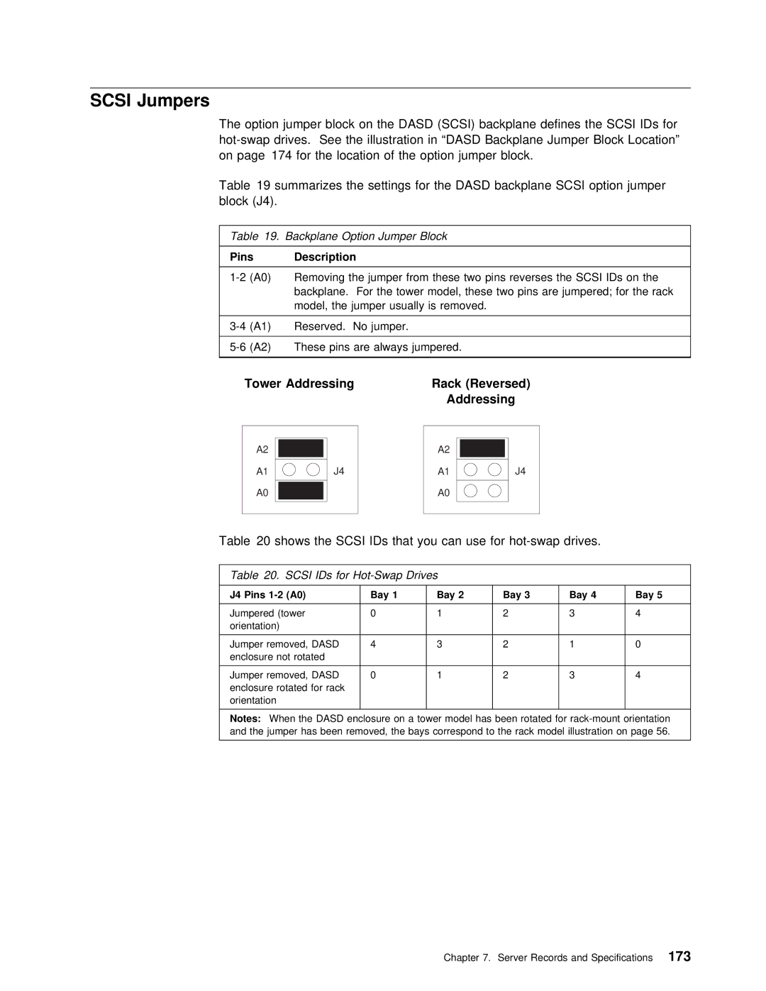
SCSI Jumpers
The | option | jumper | block on | the | DASD | (SCSI) | backplane | defines | the SCSI I | |||||
See | the | illustration | in | “DASD Backplane Jumper | Block | Loc | ||||||||
on | page 174 | for | the | location | of the | option | jumper | block. |
|
| ||||
Table 19 summarizes the settings for | the | DASD | backplane SCSI | option | jump | |||||||||
block | (J4). |
|
|
|
|
|
|
|
|
|
|
| ||
|
|
|
|
|
|
|
|
|
| |||||
Table | 19. | Backplane Option Jumper Block |
|
|
|
|
|
|
| |||||
PinsDescription
Tower Addressing | Rack (Reversed) |
| Addressing |
A2
A1
A0
A2
J4 | A1 | J4 |
A0
Table 20 shows the SCSI IDs that you can use for hot-swap drives.
Table | 20. SCSI IDs for |
|
|
|
|
|
|
| |||||||
|
|
|
|
|
|
|
|
|
|
|
|
|
| ||
J4 Pins |
| Bay | 1 |
| Bay | 2 | Bay | 3 | Bay | 4 |
| Bay 5 |
| ||
|
|
|
|
|
|
|
|
|
|
|
|
|
| ||
Jumpered | (tower | 0 |
|
| 1 |
| 2 |
| 3 |
|
| 4 |
| ||
orientation) |
|
|
|
|
|
|
|
|
|
|
|
|
| ||
|
|
|
|
|
|
|
|
|
|
|
|
|
|
| |
Jumper | removed, | DASD | 4 |
|
| 3 |
| 2 |
| 1 |
|
| 0 |
| |
enclosure | not rotated |
|
|
|
|
|
|
|
|
|
|
|
| ||
|
|
|
|
|
|
|
|
|
|
|
|
|
|
| |
Jumper | removed, | DASD | 0 |
|
| 1 |
| 2 |
| 3 |
|
| 4 |
| |
enclosure | rotated for | rack |
|
|
|
|
|
|
|
|
|
| |||
orientation |
|
|
|
|
|
|
|
|
|
|
|
|
| ||
|
|
|
|
|
|
|
|
|
|
|
| ||||
Notes: | When the | DASD | enclosure | on a | tower | model has | been | rotated for | |||||||
and the | jumper | has | been | removed, | the bays | correspond | to | the rack model illustration | |||||||
|
|
|
|
|
|
|
|
|
|
|
|
|
|
|
|
Chapter 7. Server Records and Specifications173
