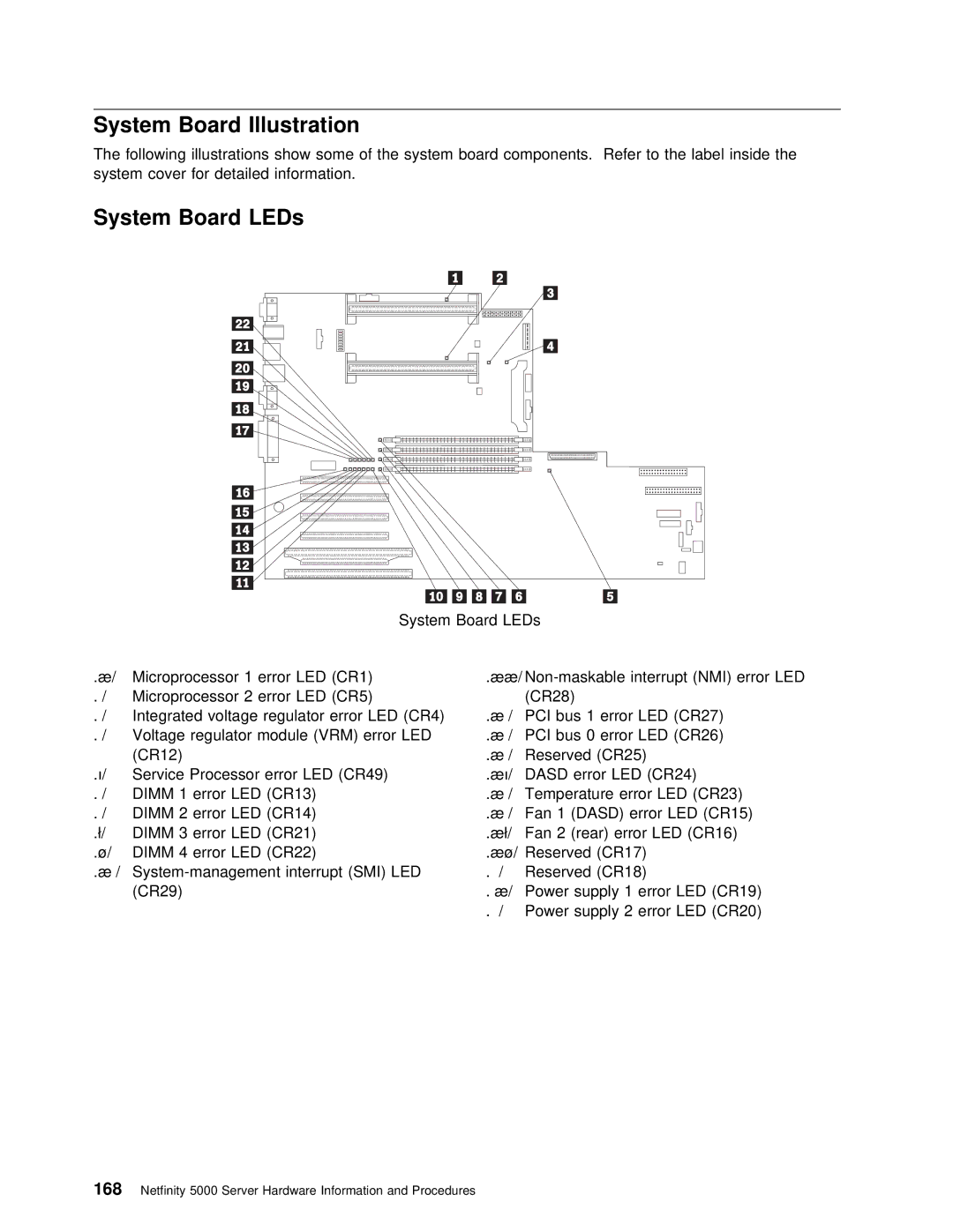
System Board Illustration
The following illustrations show some of the system board components. Refer to the label system cover for detailed information.
System Board LEDs
|
|
|
|
|
| System | Board | LEDs |
|
|
|
|
| |
.1/ | Microprocessor 1 error LED (CR1) | .11/ | ||||||||||||
.2/ | Microprocessor 2 error LED (CR5) |
| (CR28) |
|
|
|
|
| ||||||
.3/ | Integrated voltage regulator | error | LED.12/(CR4)PCI | bus 1 | error | LED | (CR27) | |||||||
.4/ | Voltage regulator module (VRM) error .13/LED | PCI bus 0 error LED (CR26) | ||||||||||||
| (CR12) |
|
|
|
| .14/ | Reserved (CR25) |
|
| |||||
.5/ | Service | Processor | error LED | (CR49) | .15/ | DASD | error LED | (CR24) |
| |||||
.6/ | DIMM | 1 | error | LED | (CR13) |
| .16/ | Temperature | error | LED | (CR23) | |||
.7/ | DIMM | 2 | error | LED | (CR14) |
| .17/ | Fan 1 | (DASD) | error | LED | (CR15) | ||
.8/ | DIMM | 3 | error | LED | (CR21) |
| .18/ | Fan 2 (rear) error LED (CR16) | ||||||
.9/ | DIMM 4 error LED (CR22) |
| .19/ | Reserved (CR17) |
|
| ||||||||
.1ð/ | .2ð/ | Reserved (CR18) |
|
| ||||||||||
| (CR29) |
|
|
|
| .21/ | Power supply 1 error LED (CR19) | |||||||
|
|
|
|
|
|
| .22/ | Power | supply | 2 | error | LED (CR20) | ||
168 Netfinity 5000 Server Hardware Information and Procedures