AT&T
Copyright 1992 AT&T
Contents
Installing the PC, CAT, or Printer
Installing Telephones and Adjuncts
Connecting the Control Unit to Network Interface
Installing Applications
Connecting Data Equipment
Initializing and Testing the System
Ordering Codes
System Numbering Forms
Unit Load Calculation Worksheet
Figures
Vi Contents
Connecting the Control Unit to the Network Interface
25. Using the D-Impact Tool to Seat the Conductors
Viii C o n t e n t s
Figure A-4 Form 2d, System Numbering-Special Renumbers
Contents
Installing Control Unit
Tables
Xii Contents
Merlin Mail
Xiv Contents
Important Safety Instructions
Xvi
Customer Support Information
Xvii
Xviii Customer Support Information
Installation and Operational Procedures
Xix
Xx Customer Support Information
Customer Support Information
Xxii Customer Support Information
Security of Your System-Preventing Toll Fraud
Xxiv Customer Support Information
Remote Administration and Maintenance
Xxvi Customer Support Information
Intended Audience
Conventions
Product Safety Labels
Type install dial #55
Telephone User Support
Related Documents
Document No Title System Documents
Document No Title
System Operator Support
Miscellaneous User Support
Documentation For Qualified Technicians
How to Comment on This Document
Introduction to Installation
Overview of the Installation Process
Tools and Equipment
Using the System Forms
System Forms
Connecting the Network Interface
Installing the Control Unit
Installing Telephones and Adjuncts
Connecting Data Equipment
Programming the System
Upgrading the Communications System
Installing the Control Unit
Overview
Preparation
Environment
Electrical Noise/Radio-Frequency Interference RFI
Environmental Requirements
Control Unit Requirements
Installing the Backboard
Backboard Requirements
Power and Grounding
AC Grounding Requirements
AC Power Requirements Parameter Value Unit
AC Outlet Tests
Using an Ideal 61-035 Circuit Tester or Equivalent
Using a Volt-Ohm Milliammeter VOM
Measuring the AC Outlet Voltages
Grounding Requirements
Central Office and AC Grounds
Approved Grounds
Central Office Trunk Protection
Heavy Lightning Protection
Connect these protectors
Installing 146A and 147A Protectors
Checking Unit Loads
Unit Loads for the Hvbrid/PBX Mode
Unit Loads
Unit Loads for Key or Behind Switch Mode
Auxiliary Power Units
Installing the Basic Carrier
Marking the Basic Carrier Screw Holes
Installing the Housing Clips on the Carrier
Upgrading the Control Unit
Removing the Control Unit Housing
Page
Page
Installing Expansion Carriers
Connecting the Carriers
Page
Installing the Power Supply
Turn off the Power
Installing a Ring Generator
Installing a Ring Generator in the Power Supply
Page
Replacing a Ring Generator
10. Replacing a Ring Generator
Page
Page
11. Installing a Copper Shield in the Power Supply
Lnstalling a Copper Shield
Page
Installing the Processor
Installing the Power Supply into Carrier
Page
Modifying the Processor for Key Mode
12. Modifying the Processor Board for Key Mode
Installing the Feature Module
13. Installing the Feature Module in the Processor
Replacing the Feature Module
Installing the Processor in the Carrier
14. Installing the Processor into the Carrier
Installing the Auxiliary Power Unit
Installing the Processor
50Installing the Processor
Replacing an Auxiliary Power Unit
Providing the Proper Grounding
Installing the Modules
Guidelines for Installing Modules
54Installing the Modules
Setting the 400EM Module DIP Switches
Signaling Type Ports 1S Default
Switch Position
Sample DIP Switches for the 400EM Module Ports Signal
Procedure
Page
17. Trunk and Telephone Jacks on Each Module
Removing a Module
Replacing Modules
Page
Connecting the Control Unit to an AC Outlet
Powering Up the System
Powering Down the System
Follow these steps in the exact sequence
Installing Telephones Adjuncts
Installing the Multi-Function Module
Multi-Function Module Packing List
MFM Installation Procedure
Remove Desk Stand and Module Cover
Page
MFM Locking Tabs
Multi-Function Module
Removing the Jack Guard
10Installing the Multi-Function Module
Powering up the Telephone after Installing the MFM
Installing Adjuncts
Page
Routing the Cords through the Cord Channel
General Purpose Adapter GPA
Answering Machines
Cordless Telephones
Credit Card Verification Terminals
Dial Dictations
Group Calling Delay Announcements
Fax Machines
Headsets
Dtmf Signaling
Loudspeaker Paging Systems
Single-Zone Paging with PagePac
Single-Zone Paging with Customer-Supplied Amplifier
10. Single-Zone Paging with Paging Access Module
Modems
Music-on-HoId, Magic On Hold
11. Single-Zone Paging with Background Music Magic On Hold
26Installing Adjuncts
Supplemental Alerts
Supplemental Alert Adapter SAA
Supplemental Alert Adapter
SAA-Compatible Alert Devices
Unsupported Telephones, Adjuncts, Adapters
Unsupported Telephones and Adjuncts Model
DCP
Installing the Direct Station Selector
DSS Installation Procedure
Installing Telephones and Adjuncts
34Installing the Direct Station Selector
Page
MLX Telephone Installation Procedure
Assembling the MLX Telephone
Page
15. Removing the Extension Label
17. Removing the Handset Holder
19. Replacing the Extension Label
D8W
Jack Plug Jack Guard Mounting Plate 630B Phone Mount
Connecting the Telephones to Control Unit
Installing Telephones and Adjuncts
Connecting up to 24 Telephones
Hardware
46Connecting the Telephones to the Control Unit
23. Tools for Connecting up to 24 Telephones
Tools
Interconnect Wiring
Telephone Installation Procedure
Connecting More than 24 Telephones
Telephone Installation Procedure More than
24. Inserting the Conductors into the Connecting Blocks
25. Using the D-Impact Tool to Seat the Conductors
26. Routing the Wires through the Wire Troughs and D-Rings
Systimax
27. Systimax Hardware Kit See also Figure
Systimax Wiring Procedure
Above floor
Green Yellow Beige Pink Grey White
30. Drilling Holes for Each Piece of Hardware
Page
31. Using the 788J1 Tool to Seat and Trim the Conductors
32. Using the Reversed Blade Edge on the 788J1 Impact Tool
Page
Wire a Telephone for Two Voice-Pairs
33. Connecting Termination Blocks to Field-Terminated Blocks
64Connecting the Telephones to the Control Unit
Terminate Cable at a Telephone Outlet
35. Pressing the Wires Over the Slots in the Outlet
Label the System Wiring
Insert Labels Color What It Identifies Special Features
Labeling 4-Pair Wire and Outlets
Color What It Identifies Special Features
Page
Checking Poorly Labeled Wiring
Remove Damaged Connecting Blocks
36. Removing the Connecting Block
Page
Connecting the Control Unit to Network Interface
Wiring
Wiring
Network Interfaces
Network Interface
Description
Adapter
Did
RJ21X Network Interface Connector
RJ21X Interface
Building the Wiring Field
RJ21X Wiring Field Hardware
RJ21X Wiring Field Hardware
RJ21X Wiring Field Tools
RJ21X Wiring Field Tools
RJ21X Wiring Field Procedure
Using the D-Impact Tool to Seat the Conductors
RJ11 and RJ14 Interfaces
RJ11 and RJ14 Interfaces
RJ11 and RJ14 Network Interface Procedure
RJ11 and RJ14 Network Interface Hardware
RJ2GX Interface
RJ48C/X Interface
Testing Trunks
Test Loop-Start Trunks
Test Ground-Stat Trunks
Procedure Labeling Trunks
Labeling Trunks
Installing the Channel Service Unit
ESF T1 CSU
Setting the CSU DIP Switches
Default Switch Settings
SW1 Default Settings Position Status
SW2 Default Settings Position Status Effect
Position Status F e c t
SW4 Default Settings Position Status Effect
SW5 Default Settings
SW6 Default Settings Position Status Effect
SW7 Settings Position Status 150 ft 150-450 ft 450-655 ft
Bit-Error Rate Threshold Option
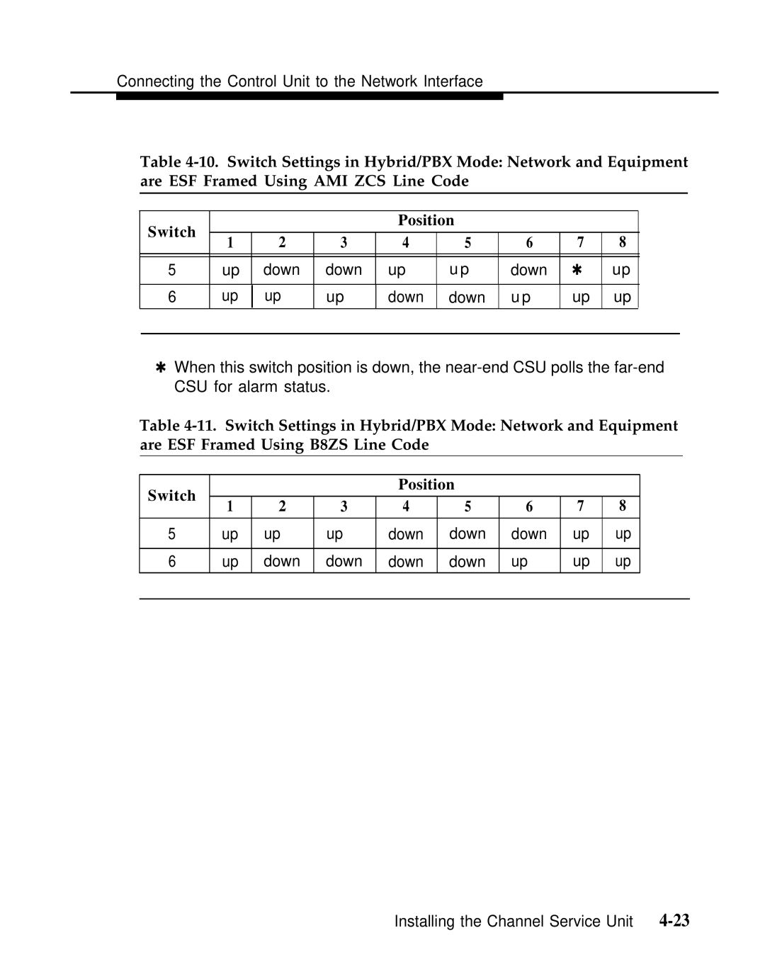
Switch Settings for Framing in Hybrid/PBX Mode
Connecting the Control Unit to the Network Interface
Set the Power Option Switch
13. Artificial Transmit Line Options Position S t a n c e
Set the Artificial Transmit Line Option
Mounting the CSU
Connecting the ESF T1 CSU
Connecting the ESF Tl CSU Rear Panel
14 D Module Pin Assignments Pin No Designation Signal
15. Wire-Wrap Connector Pin Assignments Pin No Signal
16. DTE 15-Pin Connector Pin Assignments Pin No G n a l
17. Network 15-Pin Connector Pin Assignments Pin No G n a l
ESF T1 CSU Front Panel
Plugging the CSU into an AC Outlet
L o r When Lit Indicates
18. CSU Front Panel LEDs
Network Side
System Side
CSU Front-Panel Controls
N c t i o n
20. CSU Front-Panel Test Jacks
O v i d e s
551 T1 CSU
T1 CSU
Setting the CSU DIP Switches
Signal Monitor Unit Switch Settings
Switch Setting
Office Repeater Switch Settings
23. Office Repeater Artificial Line Options Line Loss
Connecting the CSU to the Network Interface
Connecting the T1 Lines to the CSU
Inserting the Signal Monitor Unit
10. Signal Monitor Unit
Provides
24. Signal Monitor Unit Front-Panel LEDs Label Color
25. Signal Monitor Unit Front-Panel Test Jacks C k
Inserting the Office Repeater
11. Inserting the Office Repeater into the 551 Tl CSU
Connecting the 551 T1 CSU to the 100D Module
26. CSU Rear-Panel Pin Assignments 100D Module 551 T1 CSU
27. TB1 Pin Assignments Pin No Designation Signal
Plugging the CSU into an Outlet
Installing the PC, CAT, or Printer
Connecting a PC to the Control Unit
Connecting a PC Within 50 Feet
Procedure Connecting the PC Within 50 Feet
Connecting a PC 50 Feet or More
Connecting the PC Within 50 Feet
Procedure connecting the PC 50 Feet or More
Connecting the PC 50 Feet or More
Installing. the PC, CAT, or Printer
Connecting a CAT to the Control Unit
Connecting a Printer to Control Unit
Connecting a CAT and Printer on the Same AC Outlet
Procedure Connecting a CAT and Printer on the Same AC Outlet
Connecting a CAT and Printer on a Different AC Outlet
Procedure Connecting a CAT Printer on a Different AC Outlet
Page
Connecting the Printer Within 50 Feet
Connecting a Printer Within 50 Feet
Procedure Connecting the Printer Within 50 Feet
Connecting a Printer 50 Feet or More
Hardware
Connecting the Printer 50 Feet or More
Procedure Connecting the Printer 50 Feet or More
Page
248B Adapter 2012D Transformer With 248B Adapter D6AP Cord
Setting Printer Options and DIP Switches
AT&T 572 Printer Options Function Menu Status
N c t i o n Menu A t u s
Data BIT Protocol XON/XOFF Stop BIT Parity NON
AT&T 475/476 Printer DIP Switch Settings
Switch
AT&T Applications Printer DIP Switch Settings
AT&T CAT Printer DIP Switch Settings Control Switch
Connecting Data Equipment
Data Stations
Analog Data Stations
Digital Data Stations
Data Station Equipment Configurations
Data Station Configurations
Page
Analog Data and Analog Voice Equipment Configuration
Analog Data and Analog Voice Stations
Data Stations
Page
Analog Data Only Equipment Configuration
Analog Data-Only Stations
Page
Analog Data and Digital Voice Equipment Configuration
Analog Data and Digital Voice Stations
Page
Digital Data and Digital Voice Equipment Configuration
Digital Data and Digital Voice Stations
Page
Page
Digital Data-Only Equipment Configuration
Digital Data-Only Stations
Page
Hardware Requirements
Video Conferencing Data Stations
High-Speed Synchronous Enhancement Board
Page
Power Port
Video Conferencing Connections
Page
Data Module and CSU Settings
Modem Pools
Data Module Settings
Data Module Kbps Settings
Outside Data Calls Only
Data Hunt Groups
Inside and Outside Data Calls
Modem Pool Hardware Requirements
Modem Pool Configurations
Setting Up a Modem Pool
Page
Option Settings
Digital-to-Analog 7500B Settings
B Option Settings for Digital-to-Analog Modem Pool
Digital-to-Analog Modem Option Settings
Modem Option Settings for Modem Pools
Switch Bit Number
Analog-to-Digital 7500B Option Settings
B Option Settings for Analog-to-Digital Modem Pool
Analog-to-Digital Modem Option Settings
Page
Initializing and Testing System
Initializing the System
Programming Guides
Restoring from the System Programming Diskette
Upgrading the Communications System
Before You Begin
Compatibility of SPM Versions during Upgrade
Programming Compatibility
Upgrade Procedure
Page
Convert the backup file only when upgrading to Release
Upgrading from the Merlin II Communications System
Page
Setting the Time and Date
Quick-Reference Procedure
Testing the MLX Telephones
Testing the System
Troubleshooting Failed Tests
Page
Testing the MLX Telephones with a Display
Testing the MLX Telephones with an MFM
Testing the Telephones for Intercom Dial Tone
Testing the Telephones for Outside Line Dial Tone
Testing the Analog Multiline Single-Line Telephones
Initializing and Testing the System
Testing the did Trunks
Testing the Tie Trunks
Testing Two-Way Automatic-Start Tie Trunks
Testing Incoming Automatic-Start Tie Trunks
Testing Outgoing Automatic-Start Tie Trunks
Testing Two-Way Dial-Repeating Tie Trunks
Testing Incoming Dial-Repeating Tie Trunks
Testing Outgoing Dial-Repeating Tie Trunks
Testing Selected System Features
ARS and Smdr Tests
Group Calling Test
System Speed Dial Test
Testing the Operator Console
Coverage Test
Page
Testing the DSS
Testing the Night Service
Testing the Dictation System Access
Testing the Paging Interface
Testing Music-on-Hold
Testing the PFT Jacks
Ground-Start Button
Page
Testing the Touch-Tone Receivers
Installing the Control Unit Housing
Installing the Control Unit Housing
Page
Installing Applications
Voice Messaging Systems and TTRs
Considerations
TTRs Required by VMS
No. No. of 400 or
VMS ports TTRs Required Modules D u l e s
Automated Document Delivery System
Considerations and Constraints
Adds Documentation
Installation Procedure
Call Accounting System
Hardware and Software Requirements
CAS Documentation
Call Accounting Terminal
Connecting the CAT
CAT Documentation
Call Management System
Page
Lnstalling Applications
Conversant Intro
CMS Documentation
Conversant Intro Documentation
InnManager Guest Management System
InnManager Documentation
Integrated Solution
Considerations
Hardware Requirements
Merlin Attendant
IS-III Documentation
Hardware Requirements
Merlin Mail Voice Messaging System
Merlin Attendant Documentation
Merlin Mail Ports Required
Number of Ports Required Incoming Trunks Subscribers or
Page
Installing Applications
Merlin PFC
Merlin Mail VMS Documentation
PFC Documentation
Behind Switch Mode
Hybrid/PBX and Key Modes
System Programming Maintenance SPM
Installation Procedure
System Numbering Forms
Form 2a, System Numbering Station Jacks
Figure A-1. Form 2a, System Numbering-Station Jacks
Page
Form 2b, System Numbering Digital Adjuncts
Figure A-2. Form 2b, System Numbering-Digital Adjuncts
Form 2c, System Numbering Trunk Jacks
Figure A-3. Form 2c, System Numbering-Trunk Jacks
Form 2d, System Numbering Special Renumbers
Figure A-4. Form 2d, System Numbering-Special Renumbers
Unit Load Calculation Worksheet
Unit Load Worksheet
Unit Load Worksheet B-3
4Unit Load Worksheet
Unit Load Worksheet B-5
Unit Load Calculation Worksheet
Unit Load Worksheet B-7
8Unit Load Worksheet
Unit Load Calculation Worksheet
Ordering Codes
Ordering Codes
Ordering Codes C-3
4Ordering Codes
Ordering Codes C-5
6Ordering Codes
Orderlng Codes
8Ordering Codes
Ordering Codes C-9
10Ordering Codes
Ordering Codes C-11
12Ordering Codes
Ordering Codes C-13
14Ordering Codes
Ordering Codes C-15
16Ordering Codes
MLX Telephones Miscellaneous
18Ordering Codes
Ordering Codes C-19
Index
IN-2 Index
Page
IN-4 Index
Page
IN-6 Index