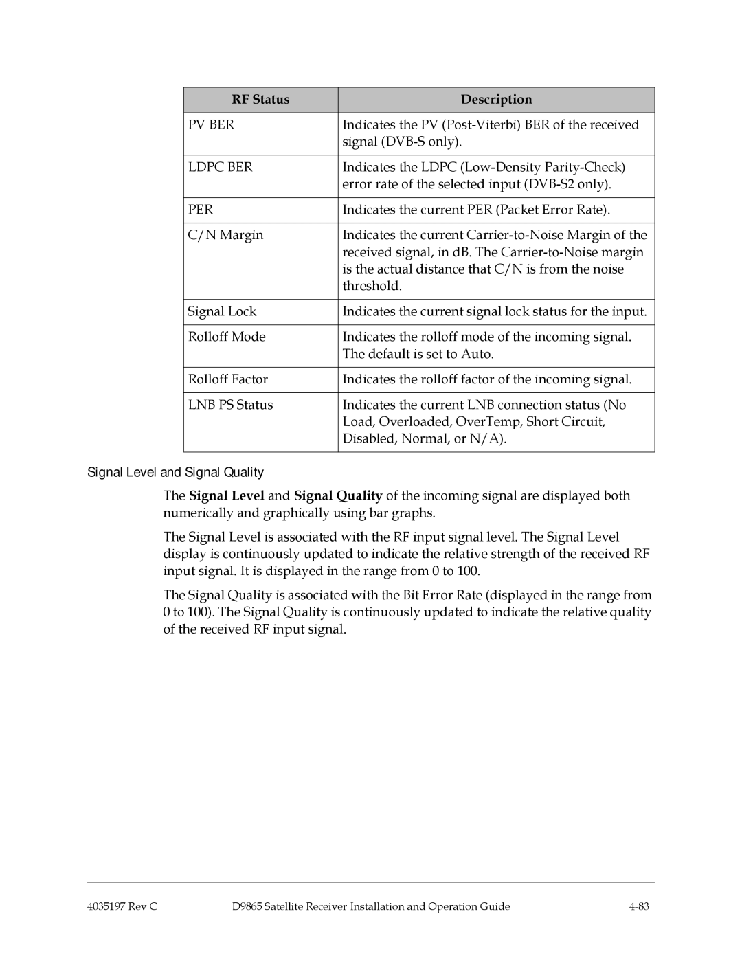
RF Status | Description |
|
|
PV BER | Indicates the PV |
| signal |
|
|
LDPC BER | Indicates the LDPC |
| error rate of the selected input |
|
|
PER | Indicates the current PER (Packet Error Rate). |
|
|
C/N Margin | Indicates the current |
| received signal, in dB. The |
| is the actual distance that C/N is from the noise |
| threshold. |
|
|
Signal Lock | Indicates the current signal lock status for the input. |
|
|
Rolloff Mode | Indicates the rolloff mode of the incoming signal. |
| The default is set to Auto. |
|
|
Rolloff Factor | Indicates the rolloff factor of the incoming signal. |
|
|
LNB PS Status | Indicates the current LNB connection status (No |
| Load, Overloaded, OverTemp, Short Circuit, |
| Disabled, Normal, or N/A). |
|
|
Signal Level and Signal Quality
The Signal Level and Signal Quality of the incoming signal are displayed both numerically and graphically using bar graphs.
The Signal Level is associated with the RF input signal level. The Signal Level display is continuously updated to indicate the relative strength of the received RF input signal. It is displayed in the range from 0 to 100.
The Signal Quality is associated with the Bit Error Rate (displayed in the range from 0 to 100). The Signal Quality is continuously updated to indicate the relative quality of the received RF input signal.
4035197 Rev C | D9865 Satellite Receiver Installation and Operation Guide |