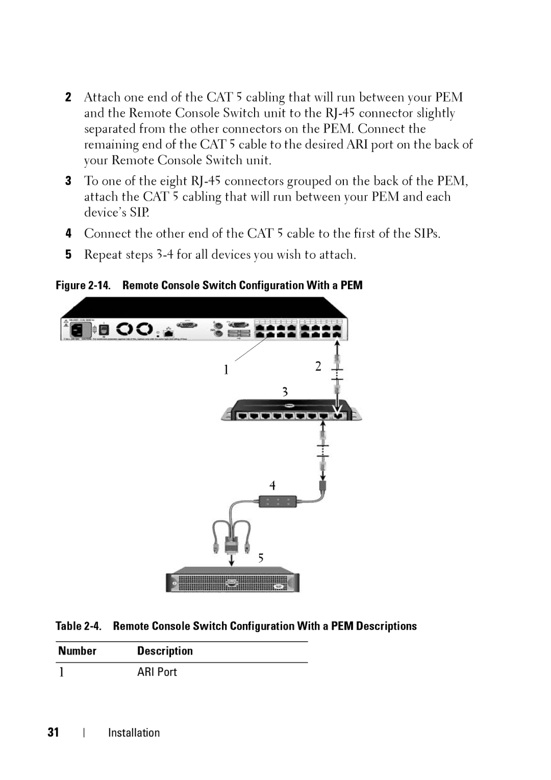
2Attach one end of the CAT 5 cabling that will run between your PEM and the Remote Console Switch unit to the RJ-45 connector slightly separated from the other connectors on the PEM. Connect the remaining end of the CAT 5 cable to the desired ARI port on the back of your Remote Console Switch unit.

3To one of the eight RJ-45 connectors grouped on the back of the PEM, attach the CAT 5 cabling that will run between your PEM and each device’s SIP.

4Connect the other end of the CAT 5 cable to the first of the SIPs.

5Repeat steps 3-4 for all devices you wish to attach.

Figure 2-14. Remote Console Switch Configuration With a PEM

Analog User

12

3

4

5

Table 2-4. Remote Console Switch Configuration With a PEM Descriptions

Number Description

1ARI Port

31

Installation

Page 48
Image 48
Dell 2321DS manual Remote Console Switch Configuration With a PEM