Signal Description
2.3PCI Bus Interface (Two Instances)
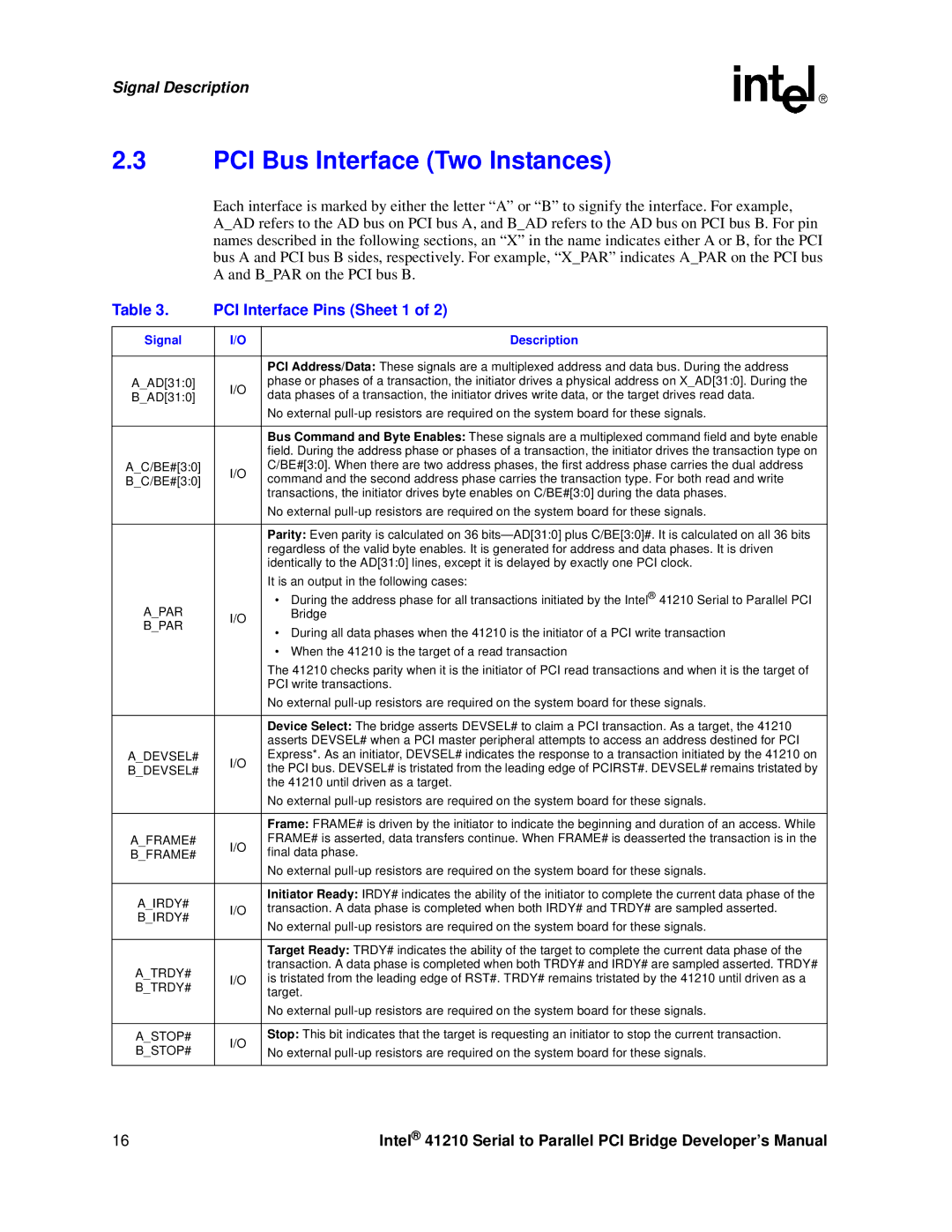
Each interface is marked by either the letter “A” or “B” to signify the interface. For example,
A_AD refers to the AD bus on PCI bus A, and B_AD refers to the AD bus on PCI bus B. For pin names described in the following sections, an “X” in the name indicates either A or B, for the PCI bus A and PCI bus B sides, respectively. For example, “X_PAR” indicates A_PAR on the PCI bus A and B_PAR on the PCI bus B.
Table 3. | PCI Interface Pins (Sheet 1 of 2) | ||
|
|
| |
Signal | I/O | Description | |
|
|
| |
|
| PCI Address/Data: These signals are a multiplexed address and data bus. During the address | |
A_AD[31:0] | I/O | phase or phases of a transaction, the initiator drives a physical address on X_AD[31:0]. During the | |
B_AD[31:0] | data phases of a transaction, the initiator drives write data, or the target drives read data. | ||
| |||
|
| No external | |
|
|
| |
|
| Bus Command and Byte Enables: These signals are a multiplexed command field and byte enable | |
|
| field. During the address phase or phases of a transaction, the initiator drives the transaction type on | |
A_C/BE#[3:0] | I/O | C/BE#[3:0]. When there are two address phases, the first address phase carries the dual address | |
B_C/BE#[3:0] | command and the second address phase carries the transaction type. For both read and write | ||
| |||
|
| transactions, the initiator drives byte enables on C/BE#[3:0] during the data phases. | |
|
| No external | |
|
|
| |
|
| Parity: Even parity is calculated on 36 | |
|
| regardless of the valid byte enables. It is generated for address and data phases. It is driven | |
|
| identically to the AD[31:0] lines, except it is delayed by exactly one PCI clock. | |
|
| It is an output in the following cases: | |
A_PAR |
| • During the address phase for all transactions initiated by the Intel® 41210 Serial to Parallel PCI | |
I/O | Bridge | ||
B_PAR | • During all data phases when the 41210 is the initiator of a PCI write transaction | ||
| |||
|
| ||
|
| • When the 41210 is the target of a read transaction | |
|
| The 41210 checks parity when it is the initiator of PCI read transactions and when it is the target of | |
|
| PCI write transactions. | |
|
| No external | |
|
|
| |
|
| Device Select: The bridge asserts DEVSEL# to claim a PCI transaction. As a target, the 41210 | |
|
| asserts DEVSEL# when a PCI master peripheral attempts to access an address destined for PCI | |
A_DEVSEL# | I/O | Express*. As an initiator, DEVSEL# indicates the response to a transaction initiated by the 41210 on | |
B_DEVSEL# | the PCI bus. DEVSEL# is tristated from the leading edge of PCIRST#. DEVSEL# remains tristated by | ||
| |||
|
| the 41210 until driven as a target. | |
|
| No external | |
|
|
| |
|
| Frame: FRAME# is driven by the initiator to indicate the beginning and duration of an access. While | |
A_FRAME# | I/O | FRAME# is asserted, data transfers continue. When FRAME# is deasserted the transaction is in the | |
B_FRAME# | final data phase. | ||
| |||
|
| No external | |
|
|
| |
A_IRDY# |
| Initiator Ready: IRDY# indicates the ability of the initiator to complete the current data phase of the | |
I/O | transaction. A data phase is completed when both IRDY# and TRDY# are sampled asserted. | ||
B_IRDY# | |||
| No external | ||
|
| ||
|
|
| |
|
| Target Ready: TRDY# indicates the ability of the target to complete the current data phase of the | |
A_TRDY# |
| transaction. A data phase is completed when both TRDY# and IRDY# are sampled asserted. TRDY# | |
I/O | is tristated from the leading edge of RST#. TRDY# remains tristated by the 41210 until driven as a | ||
B_TRDY# | |||
| target. | ||
|
| ||
|
| No external | |
|
|
| |
A_STOP# | I/O | Stop: This bit indicates that the target is requesting an initiator to stop the current transaction. | |
B_STOP# | No external | ||
| |||
|
|
| |
16 | Intel® 41210 Serial to Parallel PCI Bridge Developer’s Manual |
