Signal Description
2.7Reset Straps
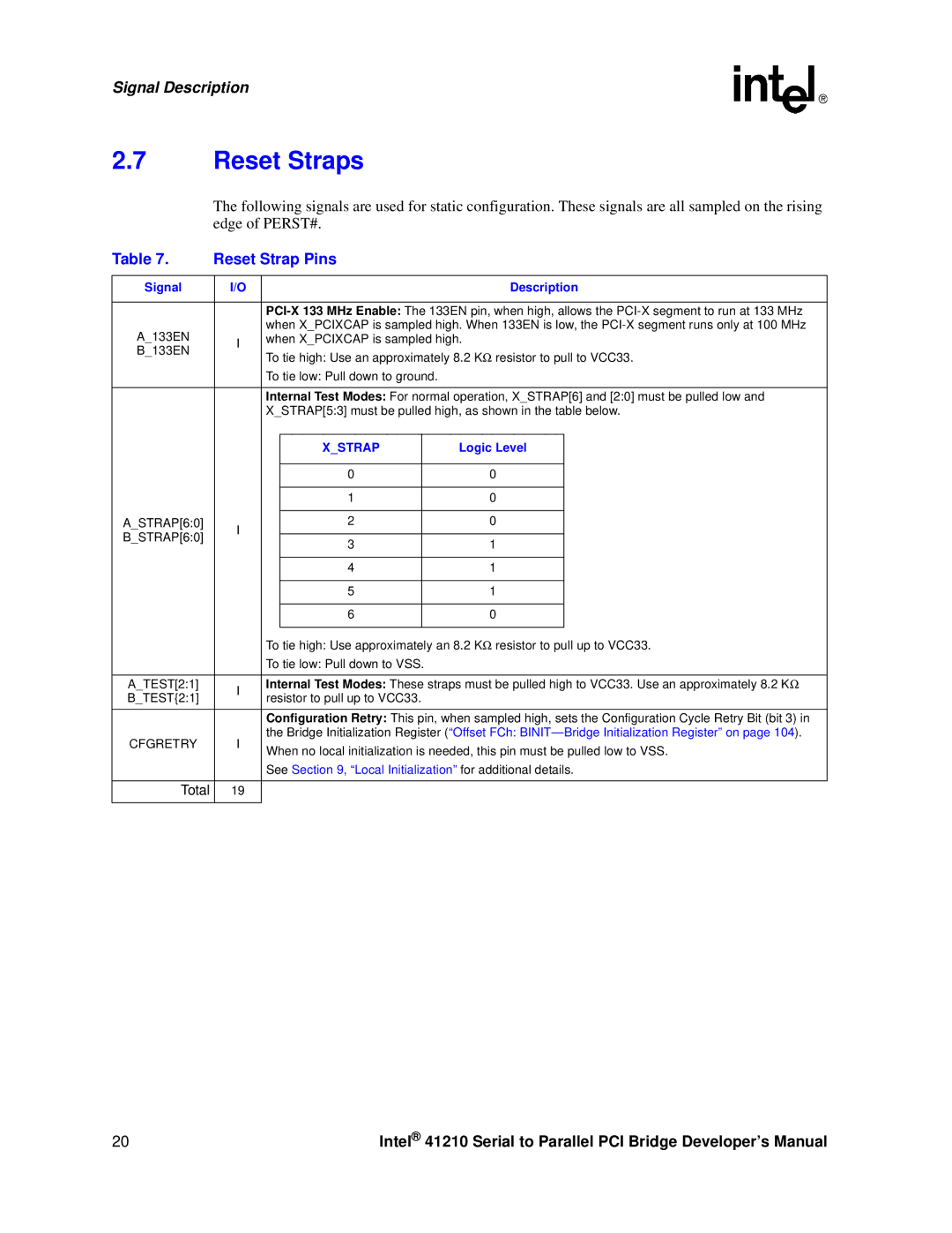
The following signals are used for static configuration. These signals are all sampled on the rising edge of PERST#.
Table 7. | Reset Strap Pins |
|
|
| ||||
|
|
|
|
|
|
|
| |
Signal | I/O |
|
|
|
| Description | ||
|
|
|
|
|
| |||
|
| |||||||
A_133EN |
| when X_PCIXCAP is sampled high. When 133EN is low, the | ||||||
I | when X_PCIXCAP is sampled high. |
|
| |||||
B_133EN | To tie high: Use an approximately 8.2 KΩ | resistor to pull to VCC33. | ||||||
| ||||||||
|
| |||||||
|
| To tie low: Pull down to ground. |
|
|
| |||
|
|
|
|
|
| |||
|
| Internal Test Modes: For normal operation, X_STRAP[6] and [2:0] must be pulled low and | ||||||
|
| X_STRAP[5:3] must be pulled high, as shown in the table below. | ||||||
|
|
|
|
|
|
| ||
|
|
| X_STRAP |
| Logic Level |
| ||
|
|
|
|
|
|
|
| |
|
|
| 0 |
|
| 0 |
| |
|
|
|
|
|
|
|
| |
|
|
| 1 |
|
| 0 |
| |
|
|
|
|
|
|
|
| |
A_STRAP[6:0] | I |
| 2 |
|
| 0 |
| |
B_STRAP[6:0] |
|
|
|
|
|
| ||
| 3 |
|
| 1 |
| |||
|
|
|
|
| ||||
|
|
|
|
|
| |||
|
|
|
|
|
|
|
| |
|
|
| 4 |
|
| 1 |
| |
|
|
|
|
|
|
|
| |
|
|
| 5 |
|
| 1 |
| |
|
|
|
|
|
|
|
| |
|
|
| 6 |
|
| 0 |
| |
|
|
|
|
|
|
| ||
|
| To tie high: Use approximately an 8.2 KΩ | resistor to pull up to VCC33. | |||||
|
| To tie low: Pull down to VSS. |
|
|
| |||
|
|
|
|
|
| |||
A_TEST[2:1] | I | Internal Test Modes: These straps must be pulled high to VCC33. Use an approximately 8.2 KΩ | ||||||
B_TEST{2:1] | resistor to pull up to VCC33. |
|
|
| ||||
|
|
|
| |||||
|
| Configuration Retry: This pin, when sampled high, sets the Configuration Cycle Retry Bit (bit 3) in | ||||||
CFGRETRY | I | the Bridge Initialization Register (“Offset FCh: | ||||||
When no local initialization is needed, this pin must be pulled low to VSS. | ||||||||
|
| |||||||
|
| See Section 9, “Local Initialization” for additional details. | ||||||
|
|
|
|
|
|
|
| |
Total | 19 |
|
|
|
|
|
| |
|
|
|
|
|
|
|
| |
20 | Intel® 41210 Serial to Parallel PCI Bridge Developer’s Manual |