|
|
|
| Register Description |
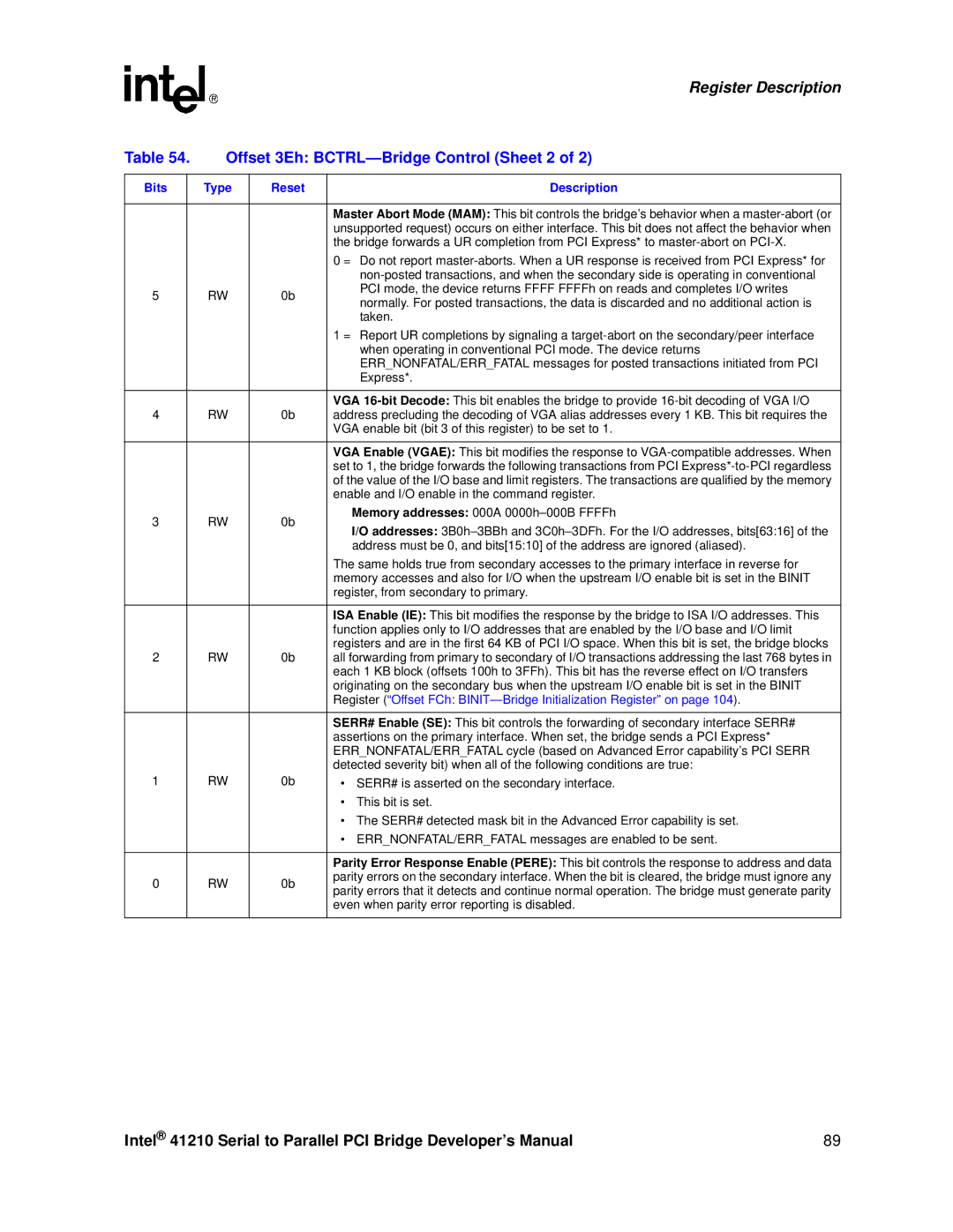
Table 54. | Offset 3Eh: | |||
|
|
|
|
|
Bits |
| Type | Reset | Description |
|
|
|
|
|
|
|
|
| Master Abort Mode (MAM): This bit controls the bridge’s behavior when a |
|
|
|
| unsupported request) occurs on either interface. This bit does not affect the behavior when |
|
|
|
| the bridge forwards a UR completion from PCI Express* to |
|
|
|
| 0 = Do not report |
|
|
|
| |
5 |
| RW | 0b | PCI mode, the device returns FFFF FFFFh on reads and completes I/O writes |
| normally. For posted transactions, the data is discarded and no additional action is | |||
|
|
|
| |
|
|
|
| taken. |
|
|
|
| 1 = Report UR completions by signaling a |
|
|
|
| when operating in conventional PCI mode. The device returns |
|
|
|
| ERR_NONFATAL/ERR_FATAL messages for posted transactions initiated from PCI |
|
|
|
| Express*. |
|
|
|
|
|
|
|
|
| VGA |
4 |
| RW | 0b | address precluding the decoding of VGA alias addresses every 1 KB. This bit requires the |
|
|
|
| VGA enable bit (bit 3 of this register) to be set to 1. |
|
|
|
|
|
|
|
|
| VGA Enable (VGAE): This bit modifies the response to |
|
|
|
| set to 1, the bridge forwards the following transactions from PCI |
|
|
|
| of the value of the I/O base and limit registers. The transactions are qualified by the memory |
|
|
|
| enable and I/O enable in the command register. |
3 |
| RW | 0b | Memory addresses: 000A |
| I/O addresses: | |||
|
|
|
| |
|
|
|
| address must be 0, and bits[15:10] of the address are ignored (aliased). |
|
|
|
| The same holds true from secondary accesses to the primary interface in reverse for |
|
|
|
| memory accesses and also for I/O when the upstream I/O enable bit is set in the BINIT |
|
|
|
| register, from secondary to primary. |
|
|
|
|
|
|
|
|
| ISA Enable (IE): This bit modifies the response by the bridge to ISA I/O addresses. This |
|
|
|
| function applies only to I/O addresses that are enabled by the I/O base and I/O limit |
2 |
| RW | 0b | registers and are in the first 64 KB of PCI I/O space. When this bit is set, the bridge blocks |
| all forwarding from primary to secondary of I/O transactions addressing the last 768 bytes in | |||
|
|
|
| each 1 KB block (offsets 100h to 3FFh). This bit has the reverse effect on I/O transfers |
|
|
|
| originating on the secondary bus when the upstream I/O enable bit is set in the BINIT |
|
|
|
| Register (“Offset FCh: |
|
|
|
|
|
|
|
|
| SERR# Enable (SE): This bit controls the forwarding of secondary interface SERR# |
|
|
|
| assertions on the primary interface. When set, the bridge sends a PCI Express* |
|
|
|
| ERR_NONFATAL/ERR_FATAL cycle (based on Advanced Error capability’s PCI SERR |
|
|
|
| detected severity bit) when all of the following conditions are true: |
1 |
| RW | 0b | • SERR# is asserted on the secondary interface. |
|
|
|
| • This bit is set. |
|
|
|
| • The SERR# detected mask bit in the Advanced Error capability is set. |
|
|
|
| • ERR_NONFATAL/ERR_FATAL messages are enabled to be sent. |
|
|
|
|
|
|
|
|
| Parity Error Response Enable (PERE): This bit controls the response to address and data |
0 |
| RW | 0b | parity errors on the secondary interface. When the bit is cleared, the bridge must ignore any |
| parity errors that it detects and continue normal operation. The bridge must generate parity | |||
|
|
|
| |
|
|
|
| even when parity error reporting is disabled. |
|
|
|
|
|
Intel® 41210 Serial to Parallel PCI Bridge Developer’s Manual | 89 |