Register Description |
| |||
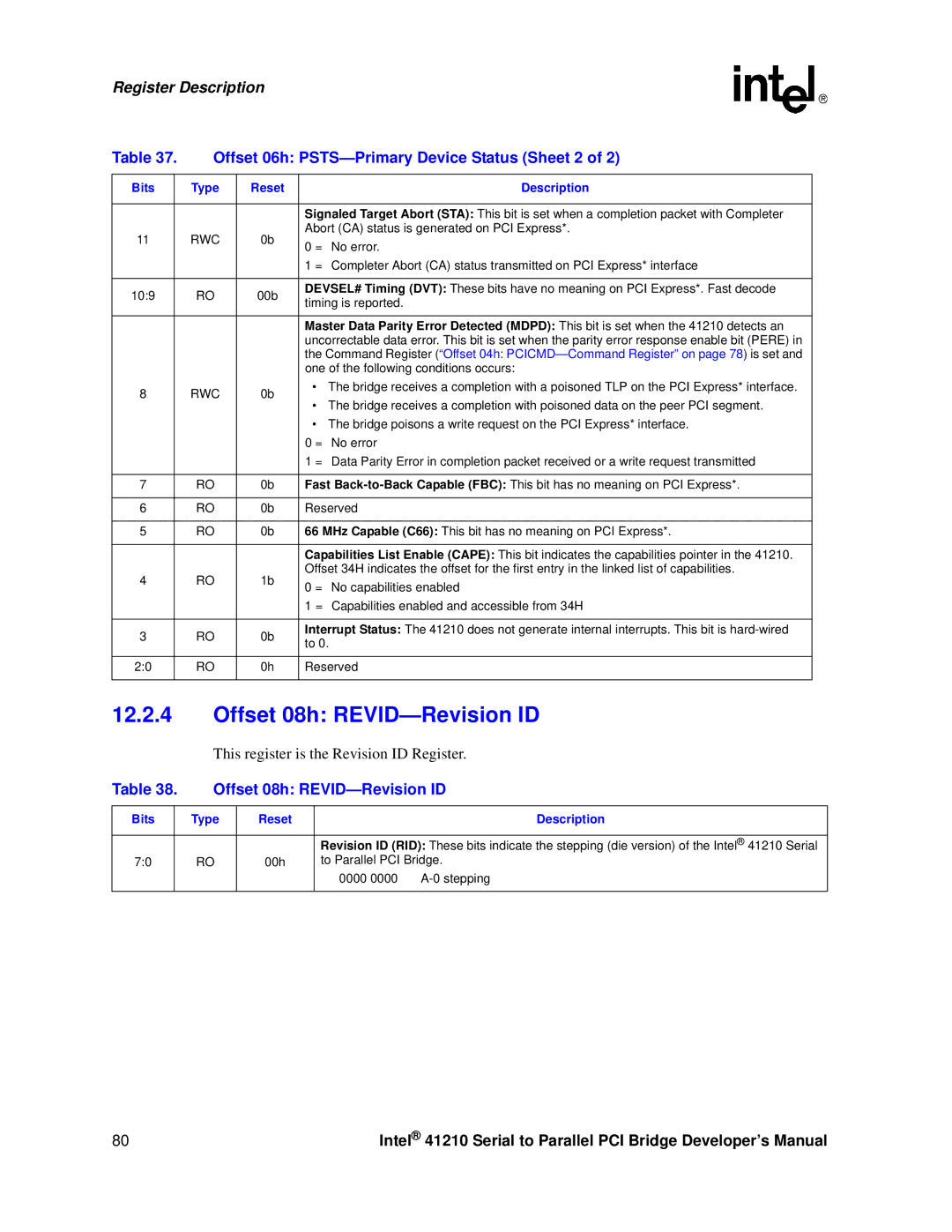
Table 37. | Offset 06h: | |||
|
|
|
|
|
Bits |
| Type | Reset | Description |
|
|
|
|
|
|
|
|
| Signaled Target Abort (STA): This bit is set when a completion packet with Completer |
11 |
| RWC | 0b | Abort (CA) status is generated on PCI Express*. |
| 0 = No error. | |||
|
|
|
| |
|
|
|
| 1 = Completer Abort (CA) status transmitted on PCI Express* interface |
|
|
|
|
|
10:9 |
| RO | 00b | DEVSEL# Timing (DVT): These bits have no meaning on PCI Express*. Fast decode |
| timing is reported. | |||
|
|
|
| |
|
|
|
|
|
|
|
|
| Master Data Parity Error Detected (MDPD): This bit is set when the 41210 detects an |
|
|
|
| uncorrectable data error. This bit is set when the parity error response enable bit (PERE) in |
|
|
|
| the Command Register (“Offset 04h: |
|
|
|
| one of the following conditions occurs: |
8 |
| RWC | 0b | • The bridge receives a completion with a poisoned TLP on the PCI Express* interface. |
| • The bridge receives a completion with poisoned data on the peer PCI segment. | |||
|
|
|
| |
|
|
|
| • The bridge poisons a write request on the PCI Express* interface. |
|
|
|
| 0 = No error |
|
|
|
| 1 = Data Parity Error in completion packet received or a write request transmitted |
|
|
|
|
|
7 |
| RO | 0b | Fast |
|
|
|
|
|
6 |
| RO | 0b | Reserved |
|
|
|
|
|
5 |
| RO | 0b | 66 MHz Capable (C66): This bit has no meaning on PCI Express*. |
|
|
|
|
|
|
|
|
| Capabilities List Enable (CAPE): This bit indicates the capabilities pointer in the 41210. |
4 |
| RO | 1b | Offset 34H indicates the offset for the first entry in the linked list of capabilities. |
| 0 = No capabilities enabled | |||
|
|
|
| |
|
|
|
| 1 = Capabilities enabled and accessible from 34H |
|
|
|
|
|
3 |
| RO | 0b | Interrupt Status: The 41210 does not generate internal interrupts. This bit is |
| to 0. | |||
|
|
|
| |
|
|
|
|
|
2:0 |
| RO | 0h | Reserved |
|
|
|
|
|
12.2.4Offset 08h: REVID—Revision ID
This register is the Revision ID Register.
Table 38. | Offset 08h: | |||
|
|
|
|
|
Bits |
| Type | Reset | Description |
|
|
|
|
|
|
|
|
| Revision ID (RID): These bits indicate the stepping (die version) of the Intel® 41210 Serial |
7:0 |
| RO | 00h | to Parallel PCI Bridge. |
|
|
|
| 0000 0000 |
|
|
|
|
|
80 | Intel® 41210 Serial to Parallel PCI Bridge Developer’s Manual |