PCI-X Interface
For controlling the priority level, there is one bit for each of the PCI REQ# inputs and one bit for the internal request input. Bit[7] in the control register is for the bridge, bit[5] is for REQ[5]#, bit[4] is for REQ[4]#, and so on. A value of 1 in a bit position puts the corresponding master in the
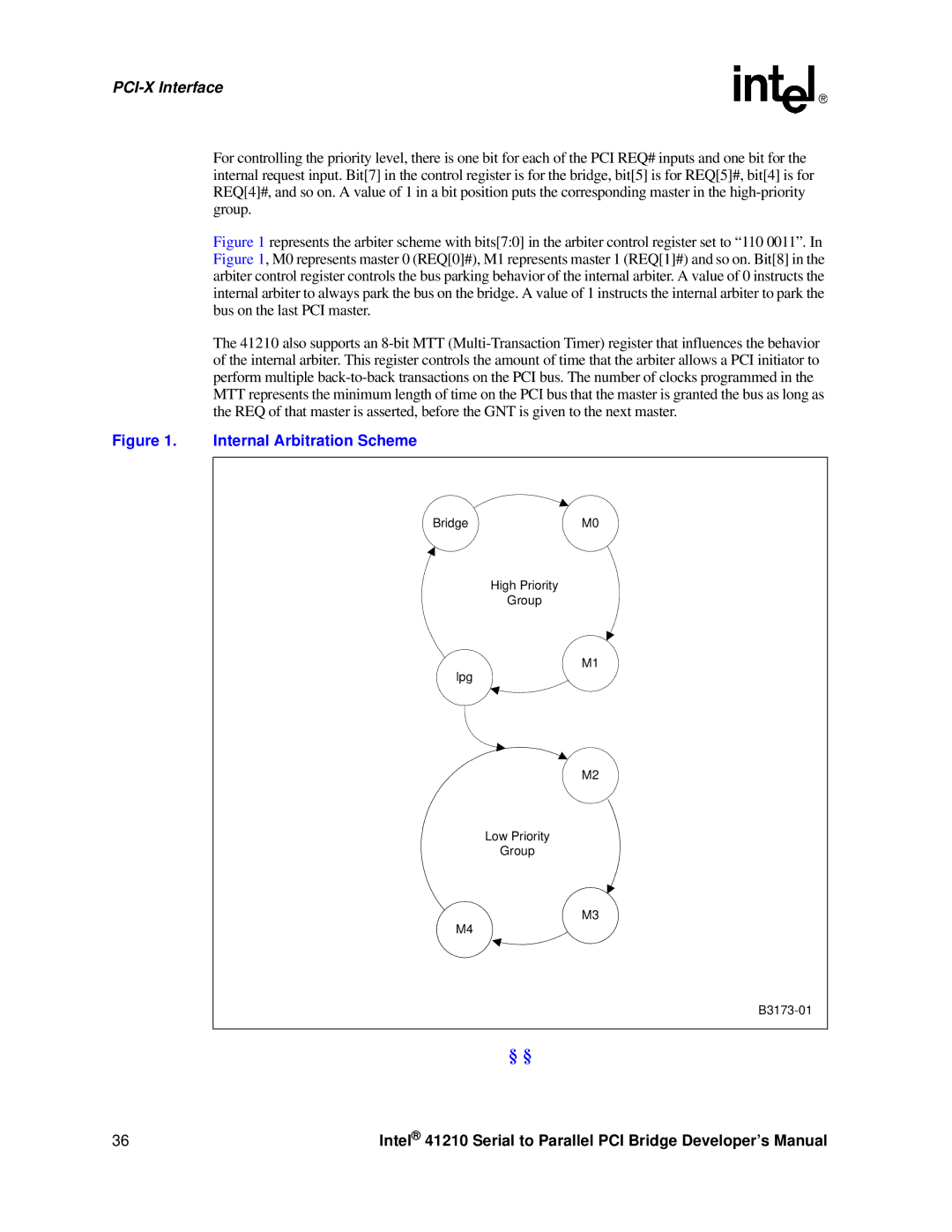
Figure 1 represents the arbiter scheme with bits[7:0] in the arbiter control register set to “110 0011”. In Figure 1, M0 represents master 0 (REQ[0]#), M1 represents master 1 (REQ[1]#) and so on. Bit[8] in the arbiter control register controls the bus parking behavior of the internal arbiter. A value of 0 instructs the internal arbiter to always park the bus on the bridge. A value of 1 instructs the internal arbiter to park the bus on the last PCI master.
The 41210 also supports an
Figure 1. Internal Arbitration Scheme
BridgeM0
High Priority
Group
M1
lpg
M2
Low Priority
Group
M3
M4
B3173-01
§ §
36 | Intel® 41210 Serial to Parallel PCI Bridge Developer’s Manual |