Register Description
12.2.20Offset 3Eh: BCTRL—Bridge Control
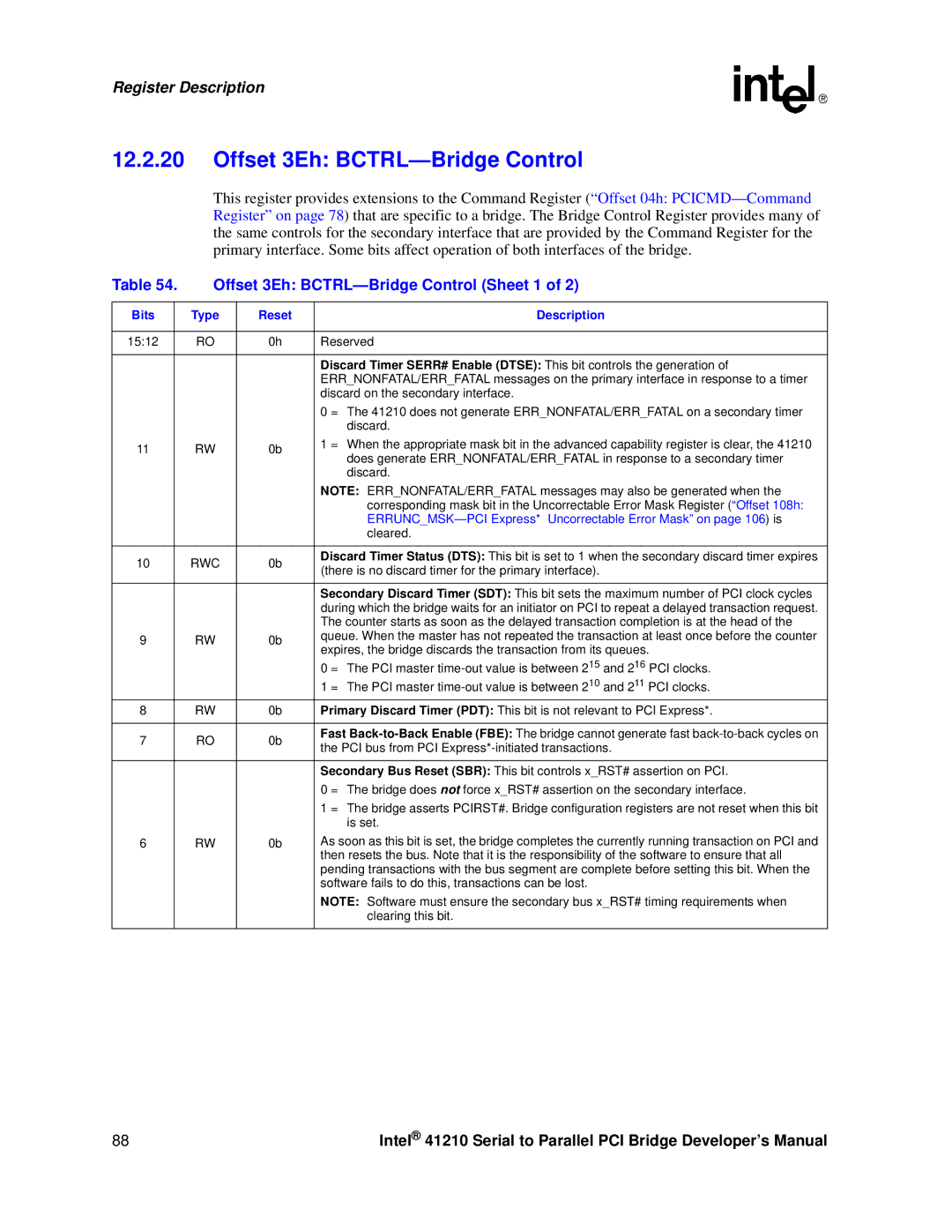
This register provides extensions to the Command Register (“Offset 04h:
Table 54. | Offset 3Eh: | |||
|
|
|
|
|
Bits |
| Type | Reset | Description |
|
|
|
|
|
15:12 |
| RO | 0h | Reserved |
|
|
|
|
|
|
|
|
| Discard Timer SERR# Enable (DTSE): This bit controls the generation of |
|
|
|
| ERR_NONFATAL/ERR_FATAL messages on the primary interface in response to a timer |
|
|
|
| discard on the secondary interface. |
|
|
|
| 0 = The 41210 does not generate ERR_NONFATAL/ERR_FATAL on a secondary timer |
|
|
|
| discard. |
11 |
| RW | 0b | 1 = When the appropriate mask bit in the advanced capability register is clear, the 41210 |
| does generate ERR_NONFATAL/ERR_FATAL in response to a secondary timer | |||
|
|
|
| |
|
|
|
| discard. |
|
|
|
| NOTE: ERR_NONFATAL/ERR_FATAL messages may also be generated when the |
|
|
|
| corresponding mask bit in the Uncorrectable Error Mask Register (“Offset 108h: |
|
|
|
| |
|
|
|
| cleared. |
|
|
|
|
|
10 |
| RWC | 0b | Discard Timer Status (DTS): This bit is set to 1 when the secondary discard timer expires |
| (there is no discard timer for the primary interface). | |||
|
|
|
| |
|
|
|
|
|
|
|
|
| Secondary Discard Timer (SDT): This bit sets the maximum number of PCI clock cycles |
|
|
|
| during which the bridge waits for an initiator on PCI to repeat a delayed transaction request. |
|
|
|
| The counter starts as soon as the delayed transaction completion is at the head of the |
9 |
| RW | 0b | queue. When the master has not repeated the transaction at least once before the counter |
| expires, the bridge discards the transaction from its queues. | |||
|
|
|
| |
|
|
|
| 0 = The PCI master |
|
|
|
| 1 = The PCI master |
8 |
| RW | 0b | Primary Discard Timer (PDT): This bit is not relevant to PCI Express*. |
|
|
|
|
|
7 |
| RO | 0b | Fast |
| the PCI bus from PCI | |||
|
|
|
| |
|
|
|
|
|
|
|
|
| Secondary Bus Reset (SBR): This bit controls x_RST# assertion on PCI. |
|
|
|
| 0 = The bridge does not force x_RST# assertion on the secondary interface. |
|
|
|
| 1 = The bridge asserts PCIRST#. Bridge configuration registers are not reset when this bit |
|
|
|
| is set. |
6 |
| RW | 0b | As soon as this bit is set, the bridge completes the currently running transaction on PCI and |
|
|
|
| then resets the bus. Note that it is the responsibility of the software to ensure that all |
|
|
|
| pending transactions with the bus segment are complete before setting this bit. When the |
|
|
|
| software fails to do this, transactions can be lost. |
|
|
|
| NOTE: Software must ensure the secondary bus x_RST# timing requirements when |
|
|
|
| clearing this bit. |
|
|
|
|
|
88 | Intel® 41210 Serial to Parallel PCI Bridge Developer’s Manual |