Signal Description
2.8SMBus Interface
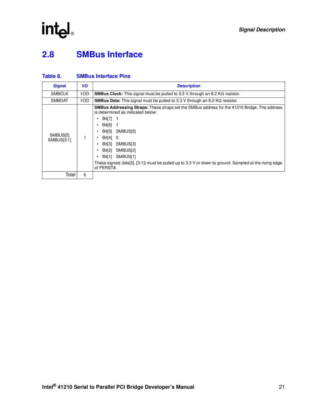
Table 8. | SMBus Interface Pins |
| |||
|
|
|
|
|
|
Signal | I/O |
|
| Description |
|
|
|
|
| ||
SMBCLK | I/OD | SMBus Clock: This signal must be pulled to 3.3 V through an 8.2 KΩ | resistor. | ||
|
|
|
| ||
SMBDAT | I/OD | SMBus Data: This signal must be pulled to 3.3 V through an 8.2 KΩ | resistor. | ||
|
|
| |||
|
| SMBus Addressing Straps: These straps set the SMBus address for the 41210 Bridge. The address | |||
|
| is determined as indicated below: |
| ||
|
| • | Bit[7] | 1 |
|
|
| • | Bit[6] | 1 |
|
SMBUS[5] |
| • | Bit[5] | SMBUS[5] |
|
I | • | Bit[4] | 0 |
| |
SMBUS[3:1] |
| ||||
| • | Bit[3] | SMBUS[3] |
| |
|
|
| |||
|
| • | Bit[2] | SMBUS[2] |
|
|
| • | Bit[1] | SMBUS[1] |
|
|
| These signals (bits[5], [3:1]) must be pulled up to 3.3 V or down to ground. Sampled at the rising edge | |||
|
| of PERST#. |
| ||
|
|
|
|
|
|
Total | 6 |
|
|
|
|
|
|
|
|
|
|
Intel® 41210 Serial to Parallel PCI Bridge Developer’s Manual | 21 |