Signal Description
2.9Miscellaneous Pins
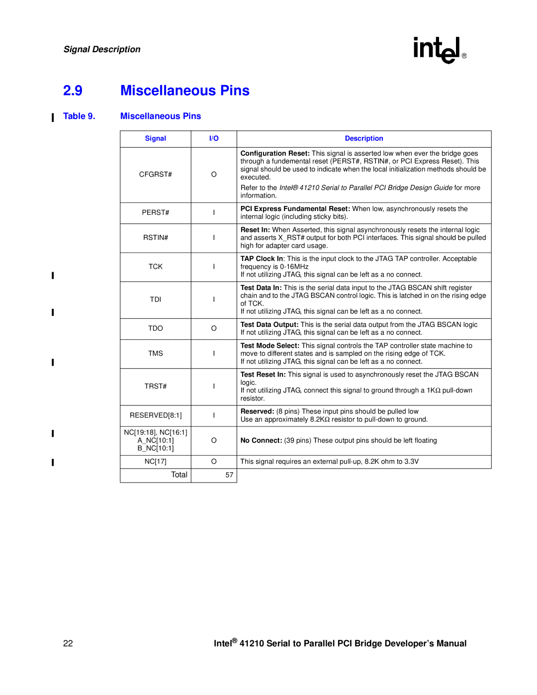
Table 9. | Miscellaneous Pins |
|
|
| |
|
|
|
|
|
|
| Signal |
| I/O |
| Description |
|
|
|
|
|
|
|
|
|
|
| Configuration Reset: This signal is asserted low when ever the bridge goes |
|
|
|
|
| through a fundemental reset (PERST#, RSTIN#, or PCI Express Reset). This |
| CFGRST# |
| O |
| signal should be used to indicate when the local initialization methods should be |
|
|
| executed. | ||
|
|
|
|
| |
|
|
|
|
| Refer to the Intel® 41210 Serial to Parallel PCI Bridge Design Guide for more |
|
|
|
|
| information. |
|
|
|
|
|
|
| PERST# |
| I |
| PCI Express Fundamental Reset: When low, asynchronously resets the |
|
|
| internal logic (including sticky bits). | ||
|
|
|
|
| |
|
|
|
|
|
|
|
|
|
|
| Reset In: When Asserted, this signal asynchronously resets the internal logic |
| RSTIN# |
| I |
| and asserts X_RST# output for both PCI interfaces. This signal should be pulled |
|
|
|
|
| high for adapter card usage. |
|
|
|
|
|
|
|
|
|
|
| TAP Clock In: This is the input clock to the JTAG TAP controller. Acceptable |
| TCK |
| I |
| frequency is |
|
|
|
|
| If not utilizing JTAG, this signal can be left as a no connect. |
|
|
|
|
|
|
|
|
|
|
| Test Data In: This is the serial data input to the JTAG BSCAN shift register |
| TDI |
| I |
| chain and to the JTAG BSCAN control logic. This is latched in on the rising edge |
|
|
| of TCK. | ||
|
|
|
|
| |
|
|
|
|
| If not utilizing JTAG, this signal can be left as a no connect. |
|
|
|
|
|
|
| TDO |
| O |
| Test Data Output: This is the serial data output from the JTAG BSCAN logic |
|
|
| If not utilizing JTAG, this signal can be left as a no connect. | ||
|
|
|
|
| |
|
|
|
|
|
|
|
|
|
|
| Test Mode Select: This signal controls the TAP controller state machine to |
| TMS |
| I |
| move to different states and is sampled on the rising edge of TCK. |
|
|
|
|
| If not utilizing JTAG, this signal can be left as a no connect. |
|
|
|
|
|
|
|
|
|
|
| Test Reset In: This signal is used to asynchronously reset the JTAG BSCAN |
| TRST# |
| I |
| logic. |
|
|
| If not utilizing JTAG, connect this signal to ground through a 1KΩ | ||
|
|
|
|
| |
|
|
|
|
| resistor. |
|
|
|
|
|
|
| RESERVED[8:1] |
| I |
| Reserved: (8 pins) These input pins should be pulled low |
|
|
| Use an approximately 8.2KΩ resistor to | ||
|
|
|
|
| |
|
|
|
|
|
|
| NC[19:18], NC[16:1] |
|
|
| No Connect: (39 pins) These output pins should be left floating |
| A_NC[10:1] |
| O |
| |
| B_NC[10:1] |
|
|
|
|
|
|
|
|
|
|
| NC[17] |
| O |
| This signal requires an external |
|
|
|
|
|
|
| Total |
|
| 57 |
|
|
|
|
|
|
|
22 | Intel® 41210 Serial to Parallel PCI Bridge Developer’s Manual |