Register Description
12.2.21Offset 40h: BCNF—Bridge Configuration Register
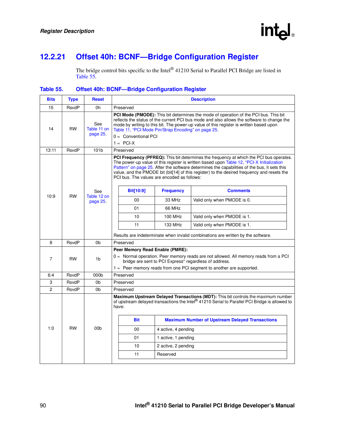
The bridge control bits specific to the Intel® 41210 Serial to Parallel PCI Bridge are listed in Table 55.
Table 55. | Offset 40h: | ||||||||
|
|
|
|
|
|
|
|
|
|
Bits |
| Type | Reset |
|
|
|
| Description | |
|
|
|
|
|
|
|
|
| |
15 |
| RsvdP | 0h | Preserved |
|
|
| ||
|
|
|
|
|
|
|
|
| |
|
|
|
| PCI Mode (PMODE): This bit determines the mode of operation of the PCI bus. This bit | |||||
|
|
| See | reflects the status of the current PCI bus mode and also allows the software to change the | |||||
|
|
| mode by writing to this bit. The | ||||||
14 |
| RW | Table 11 on | Table 11, “PCI Mode Pin/Strap Encoding” on page 25. | |||||
|
|
| page 25. | 0 = | Conventional PCI |
|
| ||
|
|
|
|
|
| ||||
|
|
|
| 1 = |
|
|
| ||
|
|
|
|
|
|
|
|
| |
13:11 |
| RsvdP | 101b | Preserved |
|
|
| ||
|
|
|
|
|
|
|
|
| |
|
|
|
| PCI Frequency (PFREQ): This bit determines the frequency at which the PCI bus operates. | |||||
|
|
|
| The | |||||
|
|
|
| Pattern” on page 25. After the software determines the capabilities of the bus, it sets this | |||||
|
|
|
| value, and the PMODE bit (bit[14] of this register) to the desired frequency and resets the | |||||
|
|
|
| PCI bus. The values are encoded as follows: | |||||
|
|
|
|
|
|
|
|
|
|
|
|
| See |
|
| Bit[10:9] | Frequency | Comments |
|
10:9 |
| RW | Table 12 on |
|
|
|
|
|
|
|
|
| 00 | 33 MHz | Valid only when PMODE is 0. |
| |||
|
|
| page 25. |
|
|
| |||
|
|
|
|
|
| 01 | 66 MHz |
|
|
|
|
|
|
|
|
|
|
|
|
|
|
|
|
|
| 10 | 100 MHz | Valid only when PMODE is 1. |
|
|
|
|
|
|
|
|
|
|
|
|
|
|
|
|
| 11 | 133 MHz | Valid only when PMODE is 1. |
|
|
|
|
|
|
|
|
|
| |
|
|
|
| Results are indeterminate when invalid combinations are written by the software. | |||||
|
|
|
|
|
|
|
|
| |
8 |
| RsvdP | 0b | Preserved |
|
|
| ||
|
|
|
|
|
|
|
|
| |
|
|
|
| Peer Memory Read Enable (PMRE): |
|
| |||
7 |
| RW | 1b | 0 = Normal operation. Peer memory reads are not allowed. All memory reads from a PCI | |||||
|
|
| bridge are sent to PCI Express* regardless of address. | ||||||
|
|
|
|
|
| ||||
|
|
|
| 1 = Peer memory reads from one PCI segment to another are supported. | |||||
|
|
|
|
|
|
|
|
| |
6:4 |
| RsvdP | 000b | Preserved |
|
|
| ||
|
|
|
|
|
|
|
|
| |
3 |
| RsvdP | 0b | Preserved |
|
|
| ||
|
|
|
|
|
|
|
|
| |
2 |
| RsvdP | 0b | Preserved |
|
|
| ||
|
|
|
|
|
|
|
|
| |
|
|
|
| Maximum Upstream Delayed Transactions (MDT): This bit controls the maximum number | |||||
|
|
|
| of upstream delayed transactions the Intel® 41210 Serial to Parallel PCI Bridge is allowed to | |||||
|
|
|
| have: |
|
|
| ||
|
|
|
|
|
|
|
|
| |
|
|
|
|
|
| Bit | Maximum Number of Upstream Delayed Transactions |
| |
1:0 |
| RW | 00b |
|
|
|
|
| |
|
|
| 00 | 4 active, 4 pending |
| ||||
|
|
|
|
|
|
|
|
| |
|
|
|
|
|
| 01 | 1 active, 1 pending |
| |
|
|
|
|
|
|
|
|
| |
|
|
|
|
|
| 10 | 2 active, 2 pending |
| |
|
|
|
|
|
|
|
|
|
|
|
|
|
|
|
| 11 | Reserved |
|
|
|
|
|
|
|
|
|
|
|
|
|
|
|
|
|
|
|
|
|
|
90 | Intel® 41210 Serial to Parallel PCI Bridge Developer’s Manual |