Register Description
12.2.63Offset
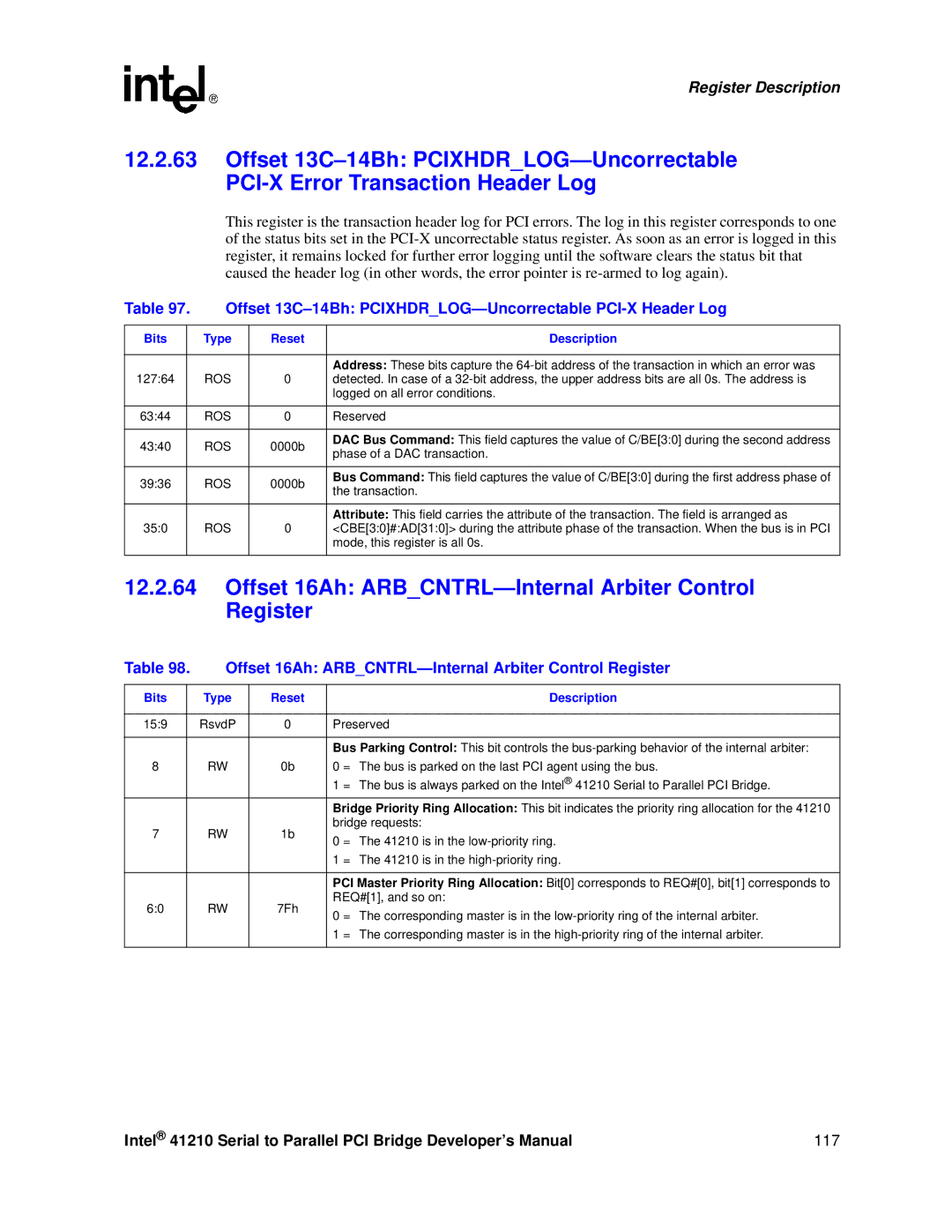
This register is the transaction header log for PCI errors. The log in this register corresponds to one of the status bits set in the
Table 97. | Offset | |||
|
|
|
|
|
Bits |
| Type | Reset | Description |
|
|
|
|
|
127:64 |
| ROS | 0 | Address: These bits capture the |
| detected. In case of a | |||
|
|
|
| logged on all error conditions. |
|
|
|
|
|
63:44 |
| ROS | 0 | Reserved |
|
|
|
|
|
43:40 |
| ROS | 0000b | DAC Bus Command: This field captures the value of C/BE[3:0] during the second address |
| phase of a DAC transaction. | |||
|
|
|
| |
|
|
|
|
|
39:36 |
| ROS | 0000b | Bus Command: This field captures the value of C/BE[3:0] during the first address phase of |
| the transaction. | |||
|
|
|
| |
|
|
|
|
|
|
|
|
| Attribute: This field carries the attribute of the transaction. The field is arranged as |
35:0 |
| ROS | 0 | <CBE[3:0]#:AD[31:0]> during the attribute phase of the transaction. When the bus is in PCI |
|
|
|
| mode, this register is all 0s. |
|
|
|
|
|
12.2.64Offset 16Ah: ARB_CNTRL—Internal Arbiter Control Register
Table 98. | Offset 16Ah: | |||
|
|
|
|
|
Bits |
| Type | Reset | Description |
|
|
|
|
|
15:9 |
| RsvdP | 0 | Preserved |
|
|
|
|
|
|
|
|
| Bus Parking Control: This bit controls the |
8 |
| RW | 0b | 0 = The bus is parked on the last PCI agent using the bus. |
|
|
|
| 1 = The bus is always parked on the Intel® 41210 Serial to Parallel PCI Bridge. |
|
|
|
| Bridge Priority Ring Allocation: This bit indicates the priority ring allocation for the 41210 |
7 |
| RW | 1b | bridge requests: |
| 0 = The 41210 is in the | |||
|
|
|
| |
|
|
|
| 1 = The 41210 is in the |
|
|
|
|
|
|
|
|
| PCI Master Priority Ring Allocation: Bit[0] corresponds to REQ#[0], bit[1] corresponds to |
6:0 |
| RW | 7Fh | REQ#[1], and so on: |
| 0 = The corresponding master is in the | |||
|
|
|
| |
|
|
|
| 1 = The corresponding master is in the |
|
|
|
|
|
Intel® 41210 Serial to Parallel PCI Bridge Developer’s Manual | 117 |
