| |
| 3 |
|
|
This section deals with the specifics of the operation and transaction flow details of the PCI interfaces.
3.1Initialization
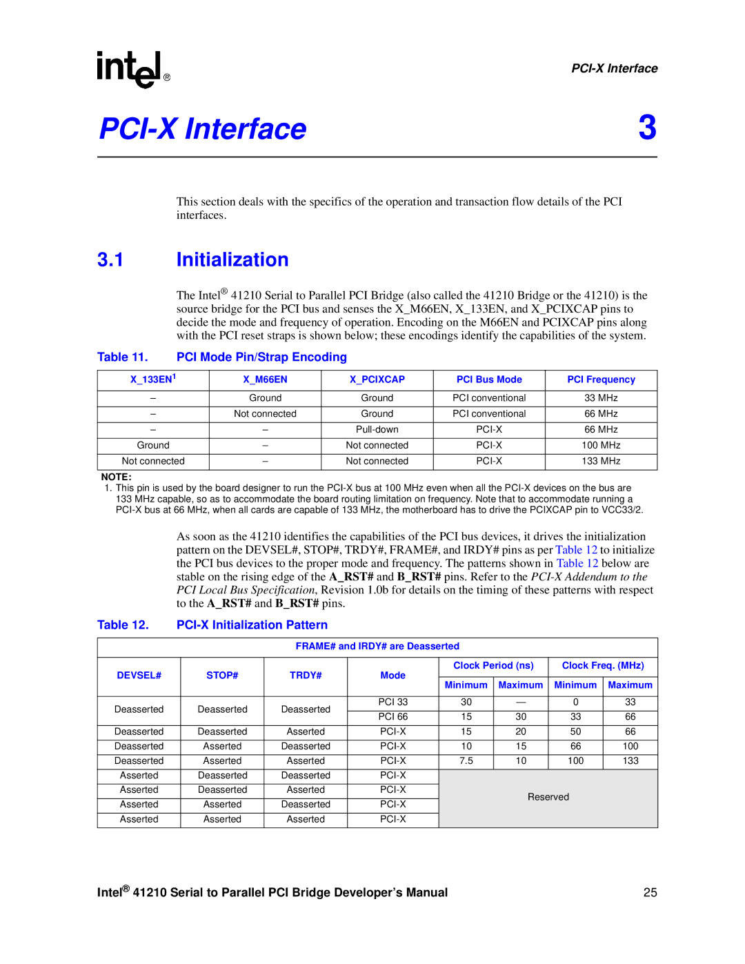
The Intel® 41210 Serial to Parallel PCI Bridge (also called the 41210 Bridge or the 41210) is the source bridge for the PCI bus and senses the X_M66EN, X_133EN, and X_PCIXCAP pins to decide the mode and frequency of operation. Encoding on the M66EN and PCIXCAP pins along with the PCI reset straps is shown below; these encodings identify the capabilities of the system.
Table 11. | PCI Mode Pin/Strap Encoding |
|
| ||
|
|
|
|
|
|
X_133EN1 |
| X_M66EN | X_PCIXCAP | PCI Bus Mode | PCI Frequency |
– |
| Ground | Ground | PCI conventional | 33 MHz |
|
|
|
|
|
|
– |
| Not connected | Ground | PCI conventional | 66 MHz |
|
|
|
|
|
|
– |
| – | 66 MHz | ||
|
|
|
|
|
|
Ground |
| – | Not connected | 100 MHz | |
|
|
|
|
| |
Not connected | – | Not connected | 133 MHz | ||
|
|
|
|
|
|
NOTE: |
|
|
|
|
|
1.This pin is used by the board designer to run the
As soon as the 41210 identifies the capabilities of the PCI bus devices, it drives the initialization pattern on the DEVSEL#, STOP#, TRDY#, FRAME#, and IRDY# pins as per Table 12 to initialize the PCI bus devices to the proper mode and frequency. The patterns shown in Table 12 below are stable on the rising edge of the A_RST# and B_RST# pins. Refer to the
Table 12. |
|
|
|
|
|
| ||
|
|
|
|
|
|
|
|
|
|
|
| FRAME# and IRDY# are Deasserted |
|
|
| ||
|
|
|
|
|
|
|
|
|
DEVSEL# |
| STOP# | TRDY# | Mode | Clock Period (ns) | Clock Freq. (MHz) | ||
|
|
|
|
| ||||
| Minimum | Maximum | Minimum | Maximum | ||||
|
|
|
|
| ||||
|
|
|
|
|
|
|
|
|
Deasserted |
| Deasserted | Deasserted | PCI 33 | 30 | — | 0 | 33 |
|
|
|
|
|
| |||
| PCI 66 | 15 | 30 | 33 | 66 | |||
|
|
|
| |||||
|
|
|
|
|
|
|
|
|
Deasserted |
| Deasserted | Asserted | 15 | 20 | 50 | 66 | |
|
|
|
|
|
|
|
|
|
Deasserted |
| Asserted | Deasserted | 10 | 15 | 66 | 100 | |
|
|
|
|
|
|
|
|
|
Deasserted |
| Asserted | Asserted | 7.5 | 10 | 100 | 133 | |
|
|
|
|
|
|
|
|
|
Asserted |
| Deasserted | Deasserted |
|
|
|
| |
|
|
|
|
|
|
|
|
|
Asserted |
| Deasserted | Asserted |
| Reserved |
| ||
|
|
|
|
|
|
| ||
Asserted |
| Asserted | Deasserted |
|
| |||
|
|
|
|
| ||||
|
|
|
|
|
|
|
|
|
Asserted |
| Asserted | Asserted |
|
|
|
| |
|
|
|
|
|
|
|
|
|
Intel® 41210 Serial to Parallel PCI Bridge Developer’s Manual | 25 |