|
| Signal Description | |
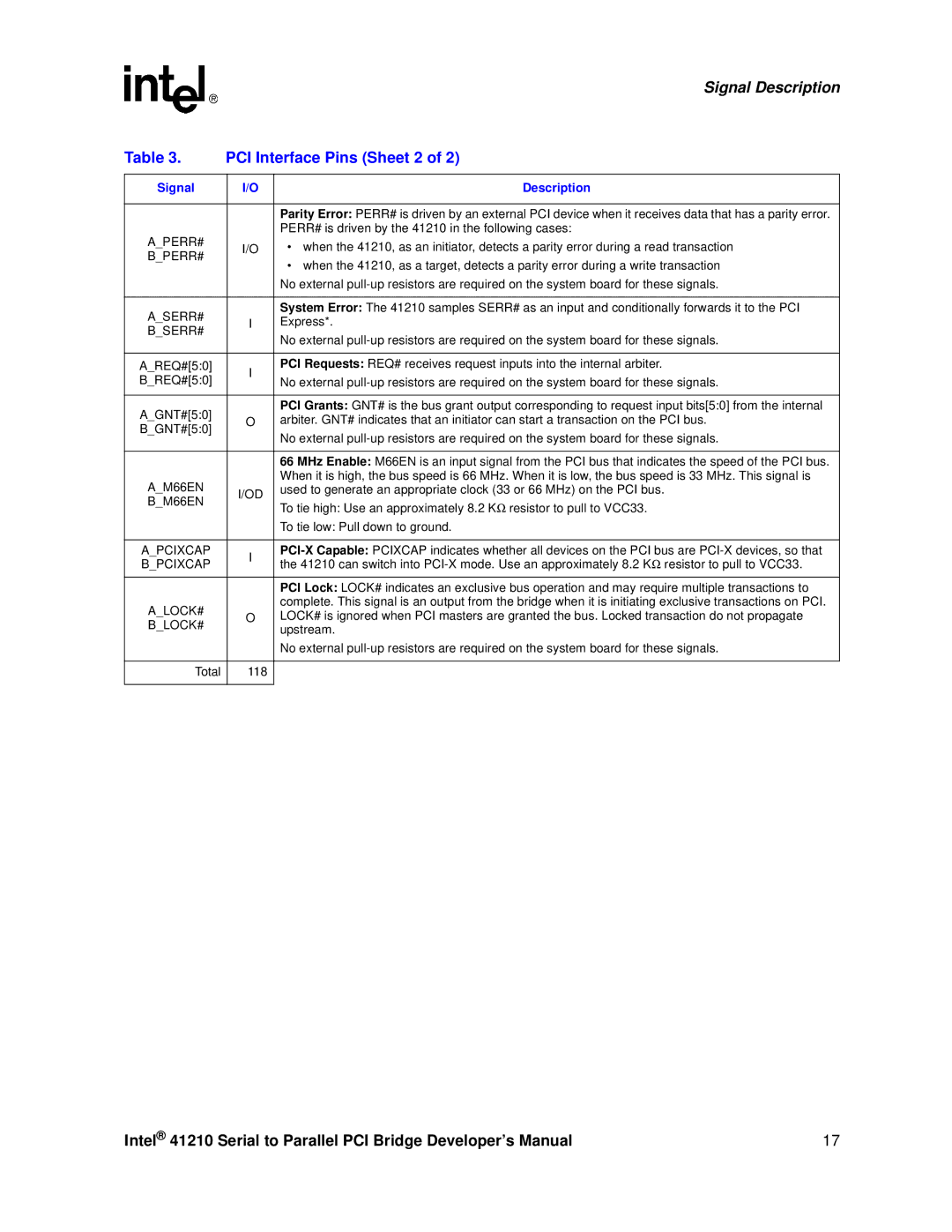
Table 3. | PCI Interface Pins (Sheet 2 of 2) | ||
|
|
| |
Signal | I/O | Description | |
|
|
| |
|
| Parity Error: PERR# is driven by an external PCI device when it receives data that has a parity error. | |
A_PERR# |
| PERR# is driven by the 41210 in the following cases: | |
I/O | • when the 41210, as an initiator, detects a parity error during a read transaction | ||
B_PERR# | |||
| • when the 41210, as a target, detects a parity error during a write transaction | ||
|
| ||
|
| No external | |
|
|
| |
A_SERR# |
| System Error: The 41210 samples SERR# as an input and conditionally forwards it to the PCI | |
I | Express*. | ||
B_SERR# | |||
| No external | ||
|
| ||
|
|
| |
A_REQ#[5:0] | I | PCI Requests: REQ# receives request inputs into the internal arbiter. | |
B_REQ#[5:0] | No external | ||
| |||
|
|
| |
A_GNT#[5:0] |
| PCI Grants: GNT# is the bus grant output corresponding to request input bits[5:0] from the internal | |
O | arbiter. GNT# indicates that an initiator can start a transaction on the PCI bus. | ||
B_GNT#[5:0] | |||
| No external | ||
|
| ||
|
|
| |
|
| 66 MHz Enable: M66EN is an input signal from the PCI bus that indicates the speed of the PCI bus. | |
A_M66EN |
| When it is high, the bus speed is 66 MHz. When it is low, the bus speed is 33 MHz. This signal is | |
I/OD | used to generate an appropriate clock (33 or 66 MHz) on the PCI bus. | ||
B_M66EN | To tie high: Use an approximately 8.2 KΩ resistor to pull to VCC33. | ||
| |||
|
| ||
|
| To tie low: Pull down to ground. | |
|
|
| |
A_PCIXCAP | I | ||
B_PCIXCAP | the 41210 can switch into | ||
| |||
|
|
| |
|
| PCI Lock: LOCK# indicates an exclusive bus operation and may require multiple transactions to | |
A_LOCK# |
| complete. This signal is an output from the bridge when it is initiating exclusive transactions on PCI. | |
O | LOCK# is ignored when PCI masters are granted the bus. Locked transaction do not propagate | ||
B_LOCK# | |||
| upstream. | ||
|
| ||
|
| No external | |
|
|
| |
Total | 118 |
| |
|
|
| |
Intel® 41210 Serial to Parallel PCI Bridge Developer’s Manual | 17 |