Interrupt Support
7.2Interrupt Routing for Devices behind a Bridge
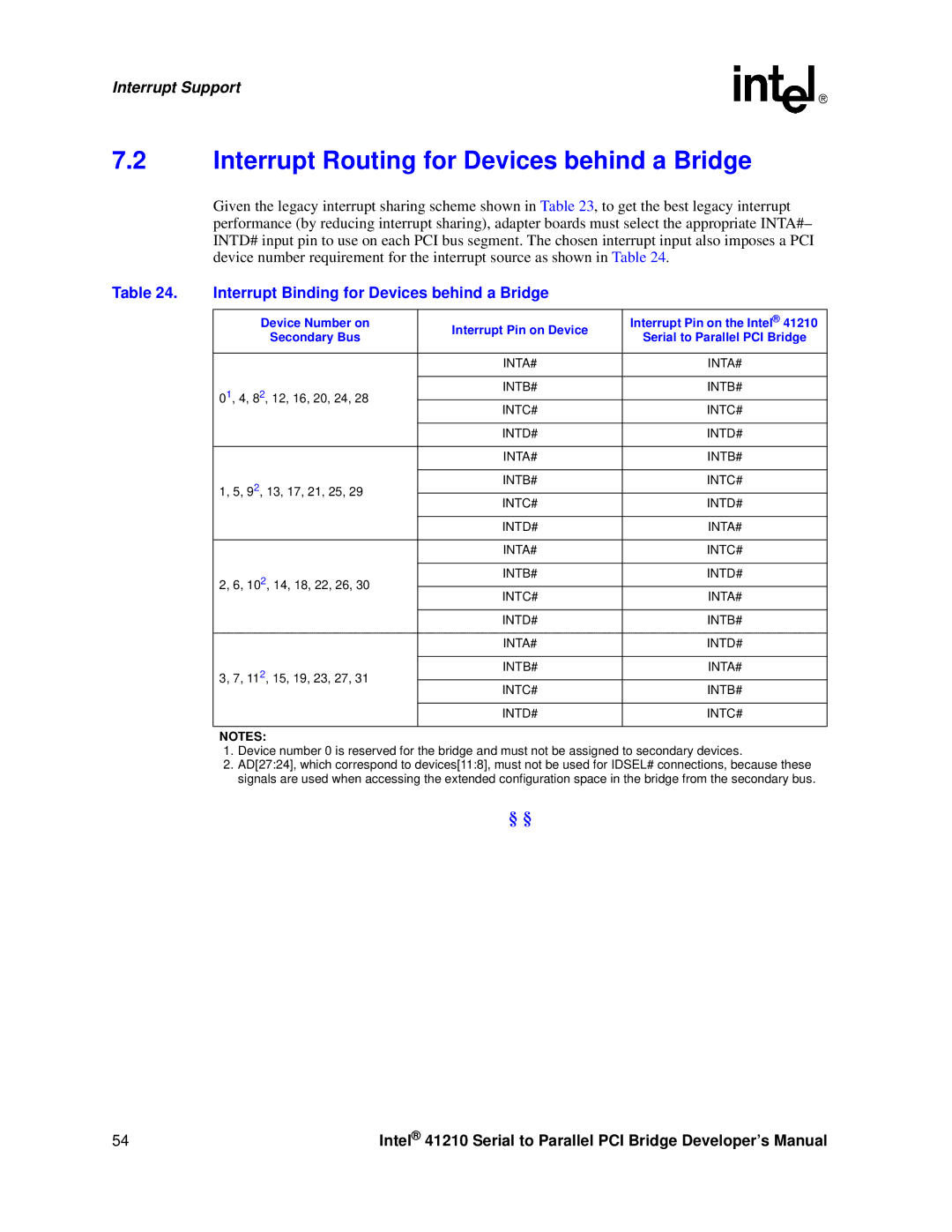
Given the legacy interrupt sharing scheme shown in Table 23, to get the best legacy interrupt performance (by reducing interrupt sharing), adapter boards must select the appropriate INTA#– INTD# input pin to use on each PCI bus segment. The chosen interrupt input also imposes a PCI device number requirement for the interrupt source as shown in Table 24.
Table 24. | Interrupt Binding for Devices behind a Bridge |
| |
|
|
|
|
| Device Number on | Interrupt Pin on Device | Interrupt Pin on the Intel® 41210 |
| Secondary Bus | Serial to Parallel PCI Bridge | |
|
| ||
|
|
|
|
|
| INTA# | INTA# |
|
|
|
|
| 01, 4, 82, 12, 16, 20, 24, 28 | INTB# | INTB# |
|
|
| |
| INTC# | INTC# | |
|
| ||
|
|
|
|
|
| INTD# | INTD# |
|
|
|
|
|
| INTA# | INTB# |
|
|
|
|
| 1, 5, 92, 13, 17, 21, 25, 29 | INTB# | INTC# |
|
|
| |
| INTC# | INTD# | |
|
| ||
|
|
|
|
|
| INTD# | INTA# |
|
|
|
|
|
| INTA# | INTC# |
|
|
|
|
| 2, 6, 102, 14, 18, 22, 26, 30 | INTB# | INTD# |
|
|
| |
| INTC# | INTA# | |
|
| ||
|
|
|
|
|
| INTD# | INTB# |
|
|
|
|
|
| INTA# | INTD# |
|
|
|
|
| 3, 7, 112, 15, 19, 23, 27, 31 | INTB# | INTA# |
|
|
| |
| INTC# | INTB# | |
|
| ||
|
|
|
|
|
| INTD# | INTC# |
|
|
|
|
| NOTES: |
|
|
1.Device number 0 is reserved for the bridge and must not be assigned to secondary devices.
2.AD[27:24], which correspond to devices[11:8], must not be used for IDSEL# connections, because these signals are used when accessing the extended configuration space in the bridge from the secondary bus.
§§
54 | Intel® 41210 Serial to Parallel PCI Bridge Developer’s Manual |