|
|
|
| Register Description |
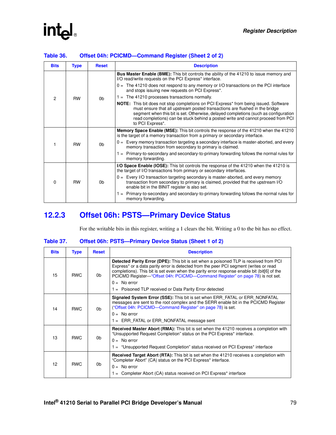
Table 36. | Offset 04h: | |||
|
|
|
|
|
Bits |
| Type | Reset | Description |
|
|
|
|
|
|
|
|
| Bus Master Enable (BME): This bit controls the ability of the 41210 to issue memory and |
|
|
|
| I/O read/write requests on the PCI Express* interface. |
|
|
|
| 0 = The 41210 does not respond to any memory or I/O transactions on the PCI interface |
|
|
|
| and stops issuing new requests on PCI Express*. |
2 |
| RW | 0b | 1 = The 41210 processes transactions normally. |
| NOTE: This bit does not stop completions on PCI Express* from being issued. Software | |||
|
|
|
| |
|
|
|
| must ensure that all upstream posted transactions are flushed in the bridge |
|
|
|
| segment when this bit is set. Otherwise, delayed completions (such as configuration |
|
|
|
| read completions) can be stuck behind a posted write and cannot proceed from PCI |
|
|
|
| to PCI Express*. |
|
|
|
|
|
|
|
|
| Memory Space Enable (MSE): This bit controls the response of the 41210 when the 41210 |
|
|
|
| is the target of a memory transaction from a primary or secondary interface. |
1 |
| RW | 0b | 0 = Every memory transaction targeting a secondary interface is |
| memory transaction from secondary to primary is claimed. | |||
|
|
|
| |
|
|
|
| 1 = |
|
|
|
| memory forwarding. |
|
|
|
| I/O Space Enable (IOSE): This bit controls the response of the 41210 when the 41210 is |
|
|
|
| the target of I/O transactions from primary or secondary interfaces. |
0 |
| RW | 0b | 0 = Every I/O transaction targeting secondary is |
| transaction from secondary to primary is claimed, provided that the upstream I/O | |||
|
|
|
| enable bit in the BINIT register is also set. |
|
|
|
| 1 = |
|
|
|
| memory forwarding. |
|
|
|
|
|
12.2.3Offset 06h: PSTS—Primary Device Status
For the writable bits in this register, writing a 1 clears the bit. Writing a 0 to the bit has no effect.
Table 37. | Offset 06h: | ||||
|
|
|
|
|
|
Bits |
| Type | Reset |
| Description |
|
|
|
|
| |
|
|
|
| Detected Parity Error (DPE): This bit is set when a poisoned TLP is received from PCI | |
|
|
|
| Express* or a data parity error is detected from the peer PCI segment (writes or read | |
15 |
| RWC | 0b | completions). This bit is set even when the parity error response enable bit (bit[6] of the | |
| PCICMD | ||||
|
|
|
| 0 = | No error |
|
|
|
| 1 = Poisoned TLP received or Data Parity Error detected | |
|
|
|
|
| |
|
|
|
| Signaled System Error (SSE): This bit is set when ERR_FATAL or ERR_NONFATAL | |
|
|
|
| messages are sent to the root complex and the SERR enable bit in the PCICMD Register | |
14 |
| RWC | 0b | (“Offset 04h: | |
| 0 = | No error | |||
|
|
|
| ||
|
|
|
| 1 = ERR_FATAL or ERR_NONFATAL message sent | |
|
|
|
|
| |
|
|
|
| Received Master Abort (RMA): This bit is set when the 41210 receives a completion with | |
13 |
| RWC | 0b | “Unsupported Request Completion” status on the PCI Express* interface. | |
| 0 = | No error | |||
|
|
|
| ||
|
|
|
| 1 = “Unsupported Request Completion” status received on PCI Express* interface | |
|
|
|
|
| |
|
|
|
| Received Target Abort (RTA): This bit is set when the 41210 receives a completion with | |
12 |
| RWC | 0b | “Completer Abort” (CA) status on the PCI Express* interface. | |
| 0 = | No error | |||
|
|
|
| ||
|
|
|
| 1 = Completer Abort (CA) status received on PCI Express* interface | |
|
|
|
|
|
|
Intel® 41210 Serial to Parallel PCI Bridge Developer’s Manual | 79 |