| Interrupt Support |
Interrupt Support | 7 |
|
|
The Intel® 41210 Serial to Parallel PCI Bridge (called hereafter the 41210 Bridge or 41210) can generate an
7.1Legacy Interrupt Sharing
PCI Express* provides interrupt messages that emulate the legacy wired mechanism. This feature allows I/O devices to signal
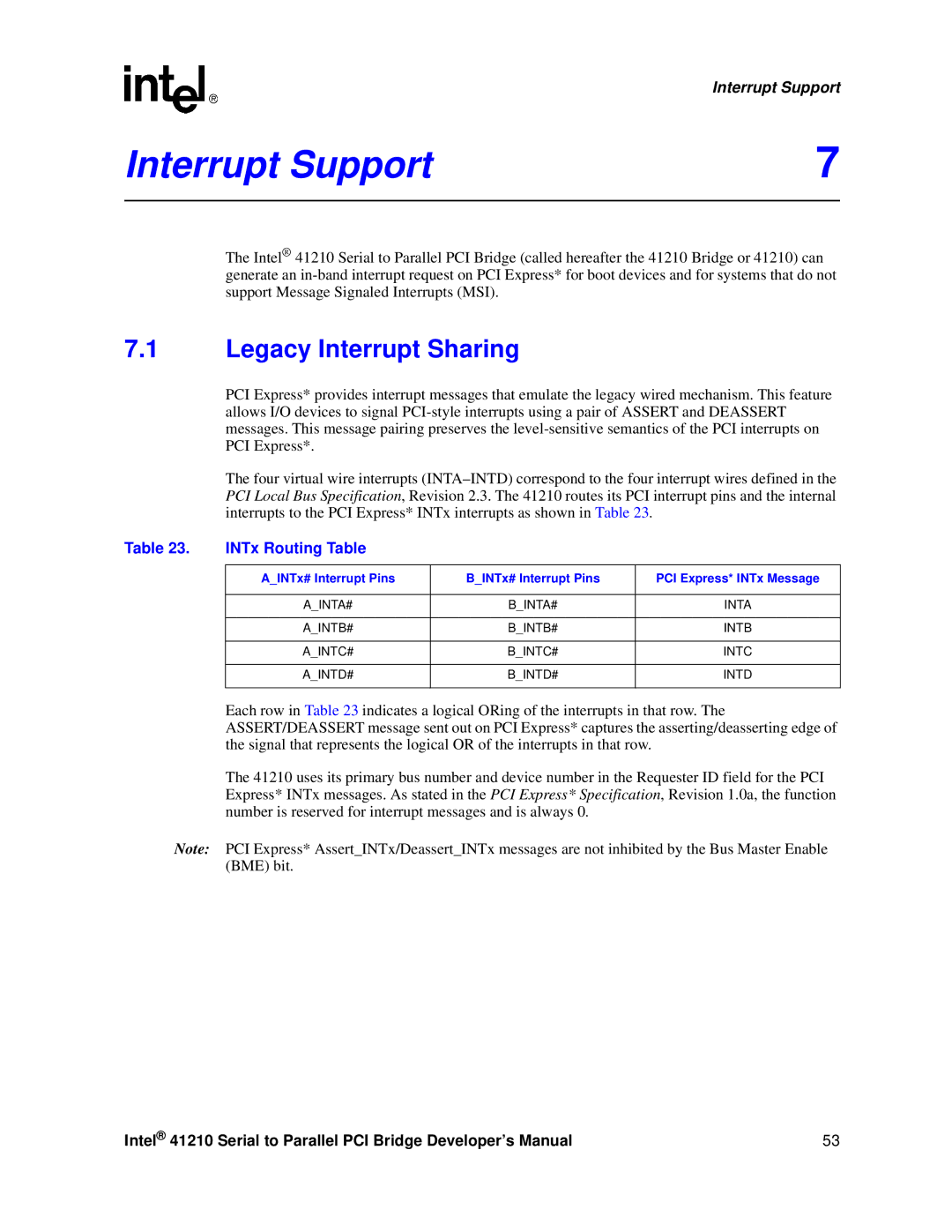
The four virtual wire interrupts
Table 23. | INTx Routing Table |
|
|
|
|
|
|
| A_INTx# Interrupt Pins | B_INTx# Interrupt Pins | PCI Express* INTx Message |
|
|
|
|
| A_INTA# | B_INTA# | INTA |
|
|
|
|
| A_INTB# | B_INTB# | INTB |
|
|
|
|
| A_INTC# | B_INTC# | INTC |
|
|
|
|
| A_INTD# | B_INTD# | INTD |
|
|
|
|
Each row in Table 23 indicates a logical ORing of the interrupts in that row. The ASSERT/DEASSERT message sent out on PCI Express* captures the asserting/deasserting edge of the signal that represents the logical OR of the interrupts in that row.
The 41210 uses its primary bus number and device number in the Requester ID field for the PCI Express* INTx messages. As stated in the PCI Express* Specification, Revision 1.0a, the function number is reserved for interrupt messages and is always 0.
Note: PCI Express* Assert_INTx/Deassert_INTx messages are not inhibited by the Bus Master Enable (BME) bit.
Intel® 41210 Serial to Parallel PCI Bridge Developer’s Manual | 53 |