Laserjet Enterprise 500 Color
Page
HP LaserJet Enterprise 500 color M551 Printers
Copyright and License
Conventions used in this guide
Conventions used in this guide
Table of contents
Removal and replacement
Vii
Enww
Enww
Solve problems 237
Enww
395
Xiii
Upgrade not performed error reading upgrade 435
Enww
457
Xvii
Parts and diagrams 525
Appendix a Service and support 575
Appendix B Product specifications 587
Appendix C Regulatory information 589
Index 601
List of tables
484
Xxiii
Xxiv
List of figures
Xxvi
22 Remove the pickup roller Tray 1 2
70 Remove the right front cover 1 118
104 Remove the residual toner feed motor 6 141
145 Remove the developing disengagement motor 2 171
186 Reinstall the PGC actuators 2 199
233 Remove the drawer connector optional paper feeder 236
35 Component locations 5 290
Xxxiv
Theory of operation
Basic operation
1Relationship between the main product systems
1Sequence of operation
Sequence of operation
Period Duration Description
Engine control system
2Engine control system
3DC controller block diagram
DC controller
Clutches
Switches
Solenoids
Component abbreviation Component name
Sensors
Motors and fans
Motors
Abbreviation Name Purpose Type Failure detection
6Motors
Abbreviation Name Cooling area Type Speed
8High voltage power supply circuits
High voltage power supply
Circuit Description
Paper
Low voltage power supply
5Low voltage power-supply circuit
9Converted DC voltages
Main DC voltage Sub-voltage Behavior
Power supply voltage detection
Safety
Sleep powersave mode
Low voltage power supply failure
10Fuser components
Power off condition
Fuser control
Type of component Abbreviation Name Function
Fuser temperature control circuit
7Fuser temperature control circuit
Fuser over temperature protection
Fuser failure detection
Laser/scanner system
8Laser/scanner system
Enww
Image formation system
9Image formation system
11Image formation process
Image formation process
Functional block Steps Description
Pre-exposure
Primary charging
Laser-beam exposure
Development
Primary transfer
Secondary transfer
Fusing
Separation
Drum cleaning
ITB cleaning
Print cartridge
Enww
Developing roller engagement and disengagement
22Developing-roller engagement and disengagement control
Enww
Intermediate transfer belt ITB unit
23 ITB unit
Primary-transfer-roller engagement and disengagement
12Primary-transfer-roller engagement states
Roller state Product state
Enww
25ITB cleaning process
Calibration
Color misregistration control
13Image-stabilization controls
Image stabilization control
Image stabilization control Description
Pickup, feed, and delivery system
Abbreviation Component
SR10
Fuser motor
30Three main units of the pickup, feed, and delivery system
Pickup-and-feed unit
31Pick feed mechanism Theory of operation
Cassette pickup
32Cassette-pickup mechanism
Cassette presence detection
33Cassette presence sensor Theory of operation
Cassette lift operation
34Cassette lift mechanism
Cassette paper presence detection
35Paper level detection mechanism Theory of operation
Cassette media width detection
36Cassette media width detection
Multifeed prevention
37Multifeed prevention
Multipurpose tray pickup
38Multipurpose tray pickup mechanism
Paper feed
39Paper-feed mechanism Theory of operation
Skew-feed prevention
40Skew-feed prevention
Fusing and delivery unit
OHT detection
Loop control
42Loop-control mechanism
Pressure-roller pressurization control
Fuser motor
Duplexing unit duplex models
44Duplexing unit
Duplexing reverse and feed control
Duplex pickup operation
17Jams that the product detects
Jam detection
Jam Description
Fuser delivery delay jam
Optional paper feeder
18Electrical components for the paper feeder
Component Abbreviation Component name Type
Paper-feeder pickup and feed operation
48Paper-feeder pickup and feed operation
Paper size detection and cassette presence detection
Paper size detection
19Paper size detection
Paper feeder cassette lift operation
50Paper-feeder cassette lift Theory of operation
Enww
Paper feeder presence detection
Paper-feeder multiple feed prevention
51Paper-feeder multiple feed prevention
Paper feeder jam detection
Removal and replacement
Removal and replacement strategy
Introduction
Electrostatic discharge
Required tools
After performing service
Service approach
Before performing service
Post service test
Parts removal order
SSD
3Parts removal order 2
Customer self repair CSR components
Print cartridges
5Remove the print cartridge 2
7Remove the duplex reverse guide 2 Removal and replacement
Duplex reverse guide
Toner collection unit
9Remove the toner collection unit 2
10Remove the toner collection unit 3
Formatter PCA
ESD sensitive component
Remove the HDD
Disk drives
Before proceeding, remove the following components
14Remove the HDD 2
Remove the SSM
Install a replacement hard drive
Reload the firmware
Tray cassette
Fuser
Pickup roller Tray
Pickup roller Tray
26Remove the pickup roller Tray 2 4 Removal and replacement
Pickup and feed rollers Tray
27Remove the Pickup and feed rollers Tray 3 1
Enww
Separation roller Tray
Secondary transfer roller
Reinstall the transfer roller
33Reinstall the transfer roller
Secondary transfer assembly
Reinstall the secondary transfer assembly
37Reinstall the secondary transfer assembly
Intermediate transfer belt ITB
Enww
Right door optional paper feeder
43Remove the right door optional paper feeder 3
Covers
Identification and location
Front door assembly
Cover on
46Remove the front door assembly 2 Removal and replacement
Right door assembly
48Remove the right door assembly 2
50Remove the right door assembly 4 Removal and replacement
52Remove the right door assembly 6
54Remove the right door assembly 8 Removal and replacement
Right rear cover
Enww
Left cover
Remove the left cover
61Remove the left cover 4 Removal and replacement
Left bottom cover
Remove the left bottom cover
Left bottom handle
Remove the left bottom handle
Hardware integration pocket HIP dn and xh models only
Control panel assembly
Enww
Right front cover
Remove the right front cover
Enww
74Remove the right front cover 5 Removal and replacement
Reinstall the power button
75Reinstall the power button
Front top cover
Remove the front top cover
Enww
Rear cover and upper rear cover
Remove the rear cover and upper rear cover
80Remove the rear cover and upper rear cover 3
Enww
Rear top cover
Remove the rear top cover
83Remove the rear top cover 2 Removal and replacement
Right bottom handle
Remove the right bottom handle
Rear bottom handle
Remove the rear bottom handle
Internal assemblies
Delivery fan, cartridge fan, and environmental sensor
Disconnect five connectors callout
Enww
Enww
Release one tab callout
Toner collection sensor
Remove the toner collection sensor
97Remove the toner collection sensor 3
Residual toner feed motor
Remove the residual toner feed motor
101Remove the residual toner feed motor 3
Enww
105Remove the residual toner feed motor 7
Reinstall the residual toner collection door
Registration density RD sensor assembly
Remove the RD sensor assembly
109Remove the RD sensor assembly 3 Removal and replacement
111Remove the RD sensor assembly 5
112Remove the RD sensor assembly 6 Removal and replacement
Power supply fan and fan duct
Remove the power supply fan and fan duct
115Remove the power supply fan 3 Removal and replacement
116Remove the power supply fan 4
Registration assembly
Remove the registration assembly
119Remove the registration assembly 3
Remove three screws callout
123Remove the registration assembly 7
Enww
Lower pickup guide
Remove the lower pickup guide
Enww
Reinstall the lower pickup guide
Interconnect board ICB
Remove the ICB
Enww
Remove the DC controller PCA
DC controller PCA and tray
ESD sensitive part
Enww
Enww
Remove the low voltage power supply
132Remove the low voltage power supply 1
Enww
Remove two screws callout
Remove the assembly
High voltage power supply lower HVPS-D
Remove the high voltage power supply lower
Enww
142Remove the high voltage power supply lower 4
Reinstall the high voltage power supply lower
Developing disengagement motor
Remove the developing disengagement motor
145Remove the developing disengagement motor 2
Pickup motor
Remove the pickup motor
Lifter drive assembly
Remove the lifter drive assembly
Enww
Automatic close assembly
Remove the automatic close assembly
Cassette pickup drive assembly
Remove the cassette pickup drive assembly
152Remove the cassette pickup drive assembly 3
Enww
156Remove the cassette pickup drive assembly 7
Enww
159Remove the cassette pickup drive assembly 10
Reinstall the cassette pickup drive assembly
Make sure that the spring callout 1 is correctly installed
Cassette pickup assembly
Remove the cassette pickup assembly
165Remove the cassette pickup assembly 3
Laser/scanner assembly Y/M
Remove the laser/scanner assembly Y/M
Enww
Enww
172Remove the laser/scanner assembly Y/M 7
Enww
176Remove the laser/scanner assembly Y/M 11
Enww
Laser/scanner assembly C/Bk
Remove the laser/scanner assembly C/Bk
Enww
Enww
183Remove the laser/scanner assembly C/Bk 6
184Remove the laser/scanner assembly C/Bk 7
Reinstall the protective glass cleaner PGC actuators
187Reinstall the PGC actuators 3
189Reinstall the PGC actuators 5 Removal and replacement
High voltage power supply upper HVPS-T
Remove the high voltage power supply upper
193Remove the high voltage power supply upper 4
Enww
Reinstall the high voltage power supply upper
195Reinstall the high voltage power supply upper
Drum motor
Remove the drum motor
Drum motor 2 or drum motor
Remove the drum motor 2 or drum motor
197Remove the drum motor 2 or drum motor
Fuser motor
Remove the fuser motor
198Remove the fuser motor
Main drive assembly
Remove the main drive assembly
Enww
204Remove the main drive assembly 6
205Remove the main drive assembly 7 Removal and replacement
Reinstall the main drive assembly
206Reinstall the main drive assembly 1
Slowly rotate the shaft near the black cam
210Reinstall the main drive assembly 5
Enww
214Reinstall the main drive assembly 9
Enww
Fuser drive assembly
Remove the fuser drive assembly
Enww
222Remove the fuser drive assembly 6 Removal and replacement
Reinstall the fuser drive assembly
223Reinstall the fuser drive assembly
Delivery assembly
Remove the delivery assembly
225Remove the delivery assembly 2
227Remove the delivery assembly 4 Removal and replacement
228Remove the delivery assembly 5
Reinstall the delivery assembly
Duplex drive assembly
Remove the duplex drive assembly
Optional paper feeder assembly Tray
Drawer connector
Remove one connector callout
Solve problems
Solve problems checklist
Solve problems checklist
Menu map
Print the menu maps
Current settings pages
Print the current settings pages
Access the Preboot menu
Preboot menu options
Cold reset using the Preboot menu
Troubleshooting flowchart
Troubleshooting process
Determine the problem source
1Troubleshooting flowchart
Power-on checks
Power subsystem
Power-on troubleshooting overview
Enww
LED diagnostics
Tools for troubleshooting
Individual component diagnostics
Understand lights on the formatter
Heartbeat LED, product initialization
Formatter to control panel communication interruptions
2Heartbeat LED, product initialization
Preboot menu
49.XX.YY error or
Connectivity LED, product operating
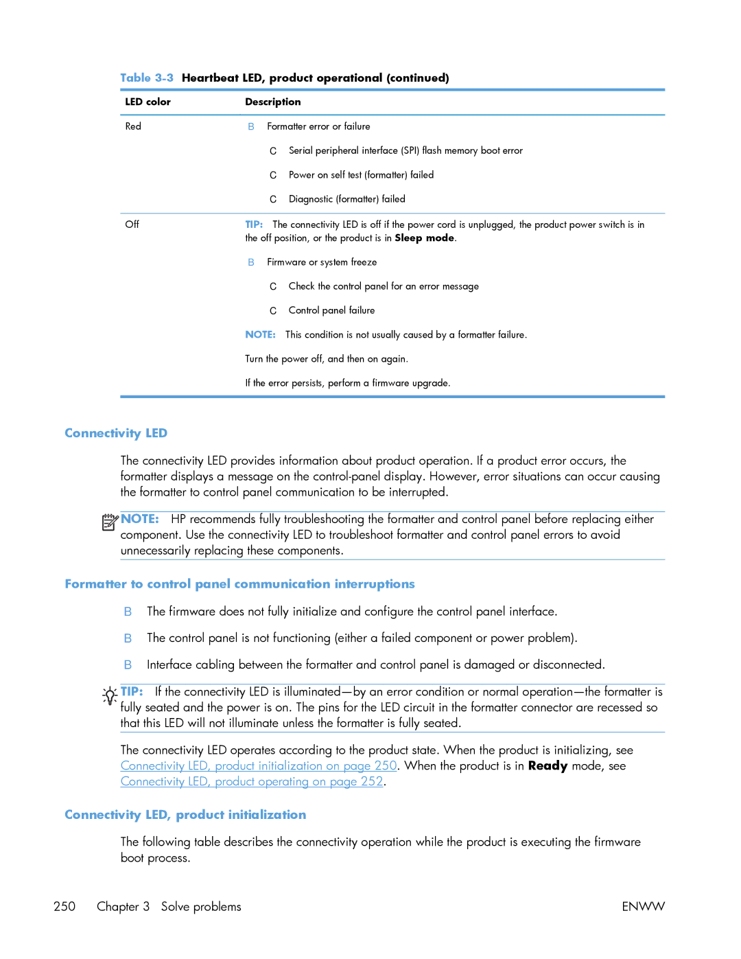
3Heartbeat LED, product operational
Connectivity LED
Connectivity LED, product initialization
4Connectivity LED, product initialization
If the error persists, perform a firmware upgrade
HP Jetdirect LEDs
5Connectivity LED, product operational
Engine diagnostics
Defeating interlocks
2Diagnostic test 2
Disable cartridge check
Administration Troubleshooting Diagnostic Tests
Engine test button
4Engine-test button
Paper path test
Paper path sensors test
6Paper-path sensors diagnostic tests
Sensor name Sensor number
Sensor or switch name Sensor or switch number
7Manual sensor diagnostic tests
Manual sensor test
Registration sensor
Fuser loop sensors
Open the right door Lower the secondary transfer assembly
Fuser output sensor
Duplexer refeed sensor
Output-bin full sensor
Fuser pressure-release sensor
ITB alienation sensor
Enww
Right- and front-door interlock switches
Enww
8Manual sensor test 2 diagnostic tests
Tray/bin manual sensor test
Tray 1 paper sensor
Tray 2 paper sensor
Tray 2 cassette sensor
Tray 2 cassette lifter sensor
Tray 3 empty sensor
Tray 3 media feed sensor
Tray 3 stack surface sensor
Print/stop test
Tray 3 media size sensors
Component test special-mode test
Component tests
9Component test details
ITB Contact/Alienation
Fuser Pressure Release Motor
Alienation Motor
TCU Motor
Diagrams
Block diagrams
10Sensors
Location of connectors
DC controller PCA
Paper feeder driver PCA
30Paper feeder driver PCA
Locations of major components
Plug/jack locations
Base product
32Component locations 2
33Component locations 3 Solve problems
34Component locations 4
2219
PCAs, motors, fans, switches, solenoids, and clutches
Location Connector Component Component name Abbreviation
13PCAs, motors, fans, switches, solenoids, and clutches
Location Connector Component abbreviation Component name
500 paper feeder
General timing chart
Timing chart
Circuit diagrams
Inter
40 Paper feeder circuit diagram
Print quality troubleshooting pages
Internal print-quality test pages
Yellow Green
44Black print-quality troubleshooting
Print quality assessment
Enww
Process a cleaning
Cleaning
Set up an auto cleaning
Configuration
Configuration
45Configuration
Security Settings information
HP embedded Jetdirect
Accessories and internal storage
Finding important information on the configuration pages
14Important information on the configuration pages
Diagnostics menu
Color band test
Print quality troubleshooting tools
Repetitive defects ruler
Calibrate the product
Sign In menu
Control panel menus
15Sign In menu
Retrieve Job From USB menu
Cancel
Retrieve Job From USB menu
Select a File or Folder
Retrieve Job From Device Memory menu
Retrieve Job From Device Memory menu
All Jobs With PIN Menu options include
17Retrieve Job From Device Memory menu
Copies
Delete Select
Copies field
Delete is
Delete Enter Pin to
Delete Delete All
Job without
Print Copies
Jobs
Supplies menu
18Supplies menu
Color Cartridges Very Low Stop Settings Prompt to Continue
Settings
Low Threshold
Low Threshold Cyan Cartridge
Settings Magenta Low Threshold Cartridge
Yellow Cartridge
Settings Specify
Settings Prompt to
Color/Black Mix Mostly Black
Mostly Color
Pages Color Pages if
Off Messages menu to
Reset Supplies New Fuser Kit Yes
Level Gauge
Enww
First level Second level Values
Trays menu
Manage Trays Use Requested Tray Exclusively First
19Trays menu
Alternative Letterhead Disabled
Disabled
Mode Enabled
Image Rotation Standard
Alternate
Tray 2 Size
Tray 1 Size
Tray 1 Type
Tray 2 Type
Reports menu
Administration menu
20Reports menu
Guide for matching printed colors
General Settings menu
General Settings menu
First level Second level Third level Fourth level Values
21General Settings menu
Wake/Auto On All Events Network port Power button Only
After
Enww
Midtones are the middle-range color- values in an image
Restore Color
Registration
X1 Shift Mm to Y1 Shift X2 Shift Default = Y2 Shift
Transparency
Adjust Paper
Print Mode
Sensing
Pre-Rotation Off Mode
Humidity Mode Normal High
Down
Paper Curl Mode Normal
Reduced
Standard.
Smooth setting
Smooth
Heavy Paper Standard
Tray Normal Alternate
Low Voltage
Background Normal Alternate
Alternate 3 setting
Alternate 1 setting
Alternate 2 setting
Alternate 2 settings
Fuser Temp Normal Alternate
Enww
Jam Recovery Auto Off
Manage Stored Quick Copy Job
Held Timeout Hour
Default Folder
Manage Stored
Enww
Retrieve From USB Settings menu
Retrieve From USB Settings menu
General Print Settings menu
General Print Settings menu
23General Print Settings menu
Font Point Size Range 4.00 Default =
Setting is 0.44 to 99.99.
Factory default setting is
Symbol Set
Default Print Options menu
24Default Print Options menu
Enww
Flip-style
Edge to Edge Enabled Disabled
Jobs. If Book-style
Display Settings menu
Display Settings menu
Manage Supplies menu
25Display Settings menu
26Manage Supplies menu
Stop The product stops until you replace the print cartridge
Enww
Different percentage for each color
Low. Continuing to
Unit Settings Prompt to
Cause an error
Print without
Settings Color/Black Mix Auto
Pages Black Pages if
Reset Supplies New Fuser Kit
Supply Messages Low Message Off
Manage Trays menu
27Manage Trays menu
Alternative Letterhead Mode Disabled
First level Values Description Use Another Tray Enabled
Blank Pages Auto Yes Override A4/Letter
28Network Settings menu
Network Settings menu
Jetdirect Menu
29Jetdirect Menu
IPv4 Settings Config Bootp Method
Manual Settings menu to configure TCP/ IPv4 parameters
Auto IP
Enww
Xxx.xxx.xx.x
Dhcp Renew Yes
Primary DNS
Secondary
Enww
Router
Router Policy Specified
Unavailable
Unavailable If
Idle Timeout
Proxy Port
Security Required
Disable IPSec
802.1x Reset
Optional
Reset Security Yes
Diagnostics Embedded LAN HW Test Yes Tests
TCP/IP
Snmp Test Yes
Http Test Yes
Data Path Test Yes
Time
Execution
Execute Yes
127.0.0.1 Dest IPv6
IPv6
Dest IPv4
Packet Size
Packets
Print Results Yes Execute
Ping Results Packets Sent
Received
RTT Max
RTT Min
RTT Average
Enww
10T Half
100TX Half or
10T Half is set
10T Full
30Troubleshooting menu
Troubleshooting menu
Exit Troubleshooting Print Event Log
Print Diagnostic
Pages Troubleshooting
Print Paper Path Print Quality Print PQ
Select Print Test
Sensors
Check
Paper Path Start Test
Paper Path Test Print Test
Test
Number of Copies Range 1 Default =
Manual Sensor
Manual Tray/Bin
Repeat Off Print/Stop Test
Calibrate/Cleaning menu
Device Maintenance menu
Backup/Restore menu
31Backup/Restore menu
Product automatically
Delay Calibration at Yes Wake/Power On
First level Second level Values Description Full Calibration
USB Firmware Upgrade menu
Memory error
10.0X.Y0 Supply memory error
Label missing
10.22.52
10.22.50
10.22.51
10.23.50
10.23.60
10.23.51
10.23.52
Printing past very low
10.XX.40 Genuine HP supplies installed
10.XX.34 Used supply in use
10.XX.41 Unsupported supply in use
10.XX.70 Printing past very low
10.YY.15 Install supply
10.YY.25 Wrong cartridge in color slot
10.YY.35 Incompatible supply
13.A3.D3
YY Internal clock error
13.00.00
13.A3.FF
13.B2.A3
13.B2.A1
13.B2.A2
13.B2.D1
13.WX.EE
13.D3.DZ
13.WX.FF
13.WX.YZ Fuser area jam
13.WX.YZ Fuser wrap jam
13.WX.YZ Jam below control panel
13.WX.YZ Jam in middle right door
13.WX.YZ Jam in right door
13.WX.YZ Jam in Tray
Insufficient memory To continue, press OK
Too complex
32.08.XX
32.1C.XX
Enww
Recommended action
Enww
32.21.00
33.XX.YY
Error
33.XX.YY Used board/disk
YZ Unexpected size in tray
YZ Unexpected type in tray
LBP OHT
YZ Error To continue, press OK
Enww
47.01.XX
42.XX.YY
47.00.XX
47.02.XX
47.04.XX
47.WX.YZ Printer calibration error To continue, press OK
47.03.XX
47.05.00
47.FC.23
49.XX.YY To continue, turn off then on
50.WX.YZ Fuser error To continue, turn off then on
Enww
Enww
YY Error
XX To continue, turn off then on
54.XX.YY Error
Recommended action 54.00.03
54.0X.0D or 54.0X.0E
55.0X.YY DC controller error To continue, turn off then on
YY DC controller error To continue, turn off then on
YY Error To continue, turn off then on
57.00.0Y Error To continue, turn off then on
58.00.04
59.05.XX
Recommended action 59.00.04 or
60.00.0Y Tray Y lifting error
59.05.08 or
61.00.01
Error To continue, turn off then on
No system To continue, turn off then on
81.0X.YY Embedded JetDirect error
Corrupt data in firmware volume
Corrupt data in job data volume
Corrupt data in solutions volume
Corrupt data in configuration volume
Upgrade not performed file is corrupt
Upgrade not performed timeout during receive
Upgrade not performed error writing to disk
Upgrade not performed error reading upgrade
Upgrade canceled by user
Upgrade not performed the file is invalid
99.00.2X
Incorrect disk
Unsupported disk
Unknown disk
Disk malfunction
Disk is not bootable please download firmware
Disk data error
No disk data installed
99.XX.YY
Supply almost full
Binname Full Remove all paper from bin
Supply low or Supplies low
Supply very low or Supplies very low
File System file operation failed To clear, press OK
Tray X lifting
File System device failure To clear, press OK
File System file system is full To clear, press OK
Accept bad signature
File System is not initialized
File System is write protected
Bad optional tray connection
Canceling... jobname
Calibration reset pending
Canceling
Checking engine
Clearing event log
Cleaning do not grab paper
Chosen personality not available To continue, press OK
Clearing paper path
Close lower right door
Creating cleaning
Close front door
Close upper right door
EIO X disk initializing
HP Secure Hard Drive disabled
Data received To print last page, press OK
Event log is empty
Incompatible supply
Incompatible supplies
Install supply Close rear door
Install supply
Install Fuser Unit
Install Transfer Unit
Install supplies
Internal disk not functional
Load Tray X Type, Size
Internal disk spinning up
Load Tray X Type, Size To use another tray, press OK
Manually feed Type, Size To use another tray, press OK
Manually feed Type, Size
Moving solenoid
Paused
No job to cancel
Moving solenoid and motor
Performing Color Band Test
Please wait
Printing Configuration
Printing Diagnostics
Printing Cmyk samples
Printing File Directory
Printing Engine Test
Printing Event Log
Printing Font List
Printing Menu Map
Printing PQ Troubleshooting
Printing Help
Printing Registration
Processing duplex job Do not grab paper until job completes
Printing Supplies Status
Printing Usage
Processing
Ready IP Address
Processing... copy X of Y
Ready
Remove all print cartridges
Remove shipping lock from Tray
Replace supply
Replace Supplies
Rotating color motor
Restore Factory Settings
Restricted from printing in color
Rotating motor
Size mismatch in Tray
Sleep mode on
Supplies in wrong positions
Tray X empty Type, Size
Tray X open
Tray X overfilled
Troubleshooting
Unsupported drive installed To continue, press OK
Type mismatch Tray
Unsupported tray configuration
Unsupported USB accessory detected Remove USB accessory
USB accessory not functional
Wrong cartridge in color slot
Event log messages
48Sample event log
Print the event log from the Service menu
Print the event log from the Administration menu
Print an event log
View an event log
View an event log from the Administration menu
Viewing the event log from the Service menu
Clear an event log
Clear jams
Product is jammed Cause Solution
Common causes of jams
Jam locations
49Jam locations
Clear jams in Tray
Enww
Clear jams in the output bin area
Clear jams in Tray
Clear jams in the right door
Enww
Enww
Enww
Enww
Clear jams in the lower right door Tray
34Causes and solutions for fuser delivery delay jams
Jam causes and solutions
33Causes and solutions for delivery delay jam
Jams in the output bin
36Causes and solutions for fuser delivery stationary jams
35Causes and solutions for wrapping jams
37Causes and solutions for residual media jams
38Causes and solutions for pickup delay jams
PCA
39Causes and solutions for pickup stationary jams
41Causes and solutions for duplex repick jams
40Causes and solutions for duplexing reverse jams
Jams in the duplex area duplex models
43Causes and solutions for pickup delay jam 1 tray pickup
42Causes and solutions for residual media jams
Jams in Tray 1, Tray 2 and internal paper path
44Causes and solutions for pickup stationary jams
45Causes and solutions for pickup delay jam 1 MP tray pickup
Jams in Tray
Change jam recovery
Paper does not feed automatically Cause Solution
Solve paper handling problems
Product feeds multiple sheets Cause Solution
Product feeds multiple sheets
Or, change the Manually Feed Prompt setting to Unless
47Print modes under the Adjust Paper Types sub menu
Select a manual print mode
Use manual print modes
48MP modes under the Optimize submenu
Uniformity Control
Tray
Background
Fuser Temp
Image defects table
Solve image quality problems
Problem Sample Cause Solution
Image defects table
49Image defects table
Clean the window and remove any
Replace the high-voltage power
Dirty, replace the ITB
Execute a Pressure roller clean
Clean the paper path
Clean the product
Set up an auto cleaning
50Solve performance problems
Solve performance problems
Problem Cause Solution
Solve direct connect problems
Solve connectivity problems
Solve network problems
Enww
Service mode functions
Service menu
Cleaning
Service ID
Cold Reset Paper
Clear Event Log
Restore factory-set defaults
Product resets
Restore factory-set defaults values
Product cold reset
Clean Disk and Partial Clean functions
Active and repository firmware locations
Reasons for performing Partial Clean
Partial Clean
Characteristics of a Partial Clean
Execute a Partial Clean
Reasons for performing Clean Disk
Clean Disk
Execute a Clean Disk
Enww
51Preboot menu options 1
Sign
Password Clear
Clean Disk
Partial Clean
Password
52Preboot menu options 2
Device
53Preboot menu options 3
External
54Preboot menu options 4
55Preboot menu options 5
Reset Password
56Preboot menu options 5
Service Tools
Jetdirect Off
Perform a firmware upgrade
Product updates
Determine the installed revision of firmware
Embedded Web Server
USB storage device Preboot menu
USB storage device control-panel menu
Enww
Parts and diagrams
Order parts, accessories, and supplies
Print cartridges and toner collection unit
Accessories
Part numbers
Memory
Customer self repair CSR and service kits
Simplex
Screws
How to use the parts lists and diagrams
Common fasteners
How to use the parts lists and diagrams
Simplex model Duplex model See Right-door assembly
External covers, panels, and doors
Description Part number Qty
Right-door assembly
Right-door assembly
Internal assemblies 1
3Internal assemblies 1
4Internal assemblies 1
Internal assemblies 2
4Internal assemblies 2
5Internal assemblies 2
Internal assemblies 3
501 25 26
6Internal assemblies 3
Internal assemblies 4
6Internal assemblies 4
7Internal assemblies 4
Internal assemblies 5
7Internal assemblies 5
8Internal assemblies 5
Cassette
Cassette
Description Part number Qty Cassette RM1-8125-000CN
Paper pickup assembly
9Paper pickup assembly
Paper pickup assembly
PCAs
10 PCAs
PCAs
Assessories
500-sheet paper feeder
500-sheet paper feeder
12Paper feeder covers Parts and diagrams
Paper feeder covers
Paper feeder covers
13Paper feeder main body Parts and diagrams
Paper feeder main body
Paper feeder main body
Paper feeder cassette
14 Cassette
Cassette
15Paper feeder PCA Parts and diagrams
Paper feeder PCA
Part number Qty
Paper feeder PCA
RM1-5839-000CN
17Alphabetical parts list
Alphabetical parts list
Description Part number
PCAs on
Duplexing unit cable assembly RM1-5730-000CN
Paper pickup assembly
Paper feeder PCA
Spring, compression RU6-2316-000CN
18Numerical parts list
Numerical parts list
Part number Description
RC2-5426-000CN Cover, front right
Part number Description
RM1-5696-000CN Waste toner detect assembly
RM1-6198-000CN Cassette assembly Tray
RM1-8167-000CN Right-door assembly simplex
Enww
Service and support
Hewlett-Packard limited warranty statement
Hewlett-Packard limited warranty statement
Enww
Enww
Data stored on the print cartridge
End User License Agreement
Transfer
Hewlett-Packard Development Company, L.P Rev /09
OpenSSL
Customer self-repair warranty service
Customer support
Product specifications
Product Height Depth Width Weight
Physical specifications
Table B-1Product dimensions
Product Height Depth Width
Regulatory information
FCC regulations
Environmental product stewardship program
Multiple returns more than one cartridge
Return and recycling instructions
United States and Puerto Rico
Single returns
Non-U.S. returns
Paper
Material restrictions
Residents of Alaska and Hawaii
Enww
Energy Use
Declaration of conformity
Supplementary Information
September
Boise, Idaho USA
For Regulatory Topics only, contact
Volatile memory
Certificate of volatility
Types of memory
Non-volatile memory
Vcci statement Japan Power cord instructions
Safety statements
Laser safety
Power cord statement Japan
EMC statement Korea Laser statement for Finland
Luokan 1 laserlaite
GS statement Germany
Restriction on Hazardous Substances statement Ukraine
Index
Cables
See also tests troubleshooting diagrams
See also jams fans
Pages
PCL
Registration density RD sensor
See also cassette
Power 244
Page
CF079-90942* *CF079-90942