Page
Conventions in this manual
How to read the Parameter Guide
About this manual
Prog 5.3 Ed-LFOs
Table of Contents
Combi 3.4 Ed-Vel Zone Velocity Zone
Sequencer mode
Combi 6.1 Ed-Arp. Arpeggiator
Combi 7.2 Ed-MasterFX
Global mode 121
Media mode 139
Effect Guide 155
Vii
Appendices 211
Viii
Bank Bank A...D, G, gd
Prog 1.1 Play
Program
Other ways to select a
1b Program Information
1c Utility
2 P.Edit Performance Editor 2a Bank, Program Select, Tempo
2b Performance Editor
3a Arpeggiator
Arp Arp. Play
2c Utility
3b Utility
1a Oscillator
Prog 2.1 Ed-Basic
Basic Prog Basic
1b Voice Assign
2a OSC1 Multisample
2 OSC1
1d Utility
2b High, Low
2d OSC1 Drum Kit
2c Octave, Transpose, Tune, Delay
2e. Utility
4a OSC 1/2 Velocity Zone
3 OSC2
4 V.Zone Velocity Zone
4b Utility
Audit. Audition
Prog 2.2 Ed-Ctrl
Ctrls Controls
1a Pitch
Prog 3.1 Ed-Pitch
1 OSC1
1b Pitch EG
2a Pitch LFO1/2 Modulation
2 OS1lfo OSC1 LFO
1c Portamento
2b Utility
5a Pitch EG
4 OS2lfo OSC2 LFO
EG Pitch EG
5b Level Mod. Level Modulation
Prog 4.1 Ed-Filter1
Basic
2 Mod.1 Filter1 Modulation1
1c B Filter B
2a Keyboard Track
2d Utility
2b Filter EG
2c AMS, Into to A, Int to B
3 Mod.2 Filter1 Modulation2
4b Filter LFO2 Modulation
LfoMod LFO Modulation
4a Filter LFO1 Modulation
4c Utility
Slope Time 00…99
Attack Time 00…99
Decay Time 00…99
Release Time 00…99
1 Lvl/Pan Level/Pan
Prog 4.2 Ed-Filter2
Prog 5.1 Ed-Amp1
1a Amp1 Level
1c AMS, Intensity
2 Mod. Amp1 Modulation
2c AMS, Int
EG Amp1 EG
2b Amp Mod., LFO1 Mod., LFO2 Mod
3a Amp1 EG
3c Time Mod. Time Modulation
3b Level Mod. Level Modulation
Off, EXT, KT
1 OS1LFO1 OSC1 LFO1
Prog 5.3 Ed-LFOs
Prog 5.2 Ed-Amp2
EG Amp2 EG
1b Freq.Mod Frequency Modulation
2 1LFO2 OSC1 LFO2
3 2LFO1 OSC2 LFO1
1c MIDI/Tempo Sync Frequency MIDI/Tempo Sync
Prog 6.1 Ed-Arp. Arpeggiator
Setup Arpeg. Setup 1a Arpeggiator Setup
4 2LFO2 OSC2 LFO2
1b Arpeggiator Tempo
Zone Scan Zone
2a Scan Zone
1 BUS
1b Use DKit Setting
Prog 7.1 Ed-InserFX
1a BUS
2b Routing
Setup
2a InsertFX Setup
IFX Insert Effect
1b Chain
1a Master Effect Setup
Prog 7.2 Ed-MasterFX
1c Master EQ Gain dB
4a Utility
MEQ Master EQ
MFX 1 Master Effect1 MFX 2 Master Effect2
23a Utility
Page
1a Bank, Combi Select, Category, Cat.Hold, 10’s Hold, Tempo
Combi 1.1 Play
Combi Combination
Bank Bank Select Bank A…C
Write Combination
1b Combination Information
Cat.HOLD
Solo Selected Timbre
2b Timbre Number & Category
Prog Timbre Program
2a Bank, Combi Select, Cat.Hold, 10’s Hold, Tempo
2c Program Select, Program Name
Mix Mixer
3a Pan, Volume
Volume 000...127
Pan
Combi 2.1 Ed-Prog/Mixer
Midi
Combi 2.2 Ed-Ctrl
Combi 3.1 Ed-Param1
1a Status, Midi Channel, BankEX2 MSB/LSB
2a Force OSC Mode, OSC Select, Portamento
2 OSC
Pitch
3a Transpose, Detune, Bend Range
Other
1a Delay ms, Use Prog’s Scale
Combi 3.2 Ed-Param2
1b Combi’s Scale, Key, Random
Slope Key Slope
Combi 3.3 Ed-Key Zone
Key Key Zone
Review
Combi 3.4 Ed-Vel Zone
Midi 1-1MIDI Filter 1a Program Change, After Touch
Combi 4.1 Ed-MIDI Filter1
Combi 4.2 Ed-MIDI Filter2
Midi 1-2MIDI Filter 2a Damper CC#64, Portamento SW CC#65
Combi 4.3 Ed-MIDI Filter3
Combi 4.4 Ed-MIDI Filter4
1a Arpeggiator Run, Tempo
Combi 6.1 Ed-Arp. Arpeggiator
1b Assign
23b Tempo
23a Arpeggiator-AB Setup
2 Arp. a Arpeggiator a 3 Arp. B Arpeggiator B
23c Utility
1a BUS Select, Send1MFX1, Send2MFX2
Combi 7.1 Ed-InsertFX
4a Scan Zone A/B
BUS Select DKit, L/R, IFX, 1, 2, 1/2, Off
DKit IFX Patch DrumKit IFX Patch
2a Ed-InsertFX Setup
2b Control Channel
Control Channel Ch01...16, G ch, All Rt
2c Routing Map, BUS Select
1a MasterFX Setup
Combi 7.2 Ed-MasterFX
1b MasterFX Chain
2 MFX1 Master Effect1 3 MFX2 Master Effect2
1d Master EQ Gain dB
1e Utility
Low 18.0...+18.0 Mid High
Sequencer mode
SEQ 1.1 Play/REC
1a Location, Meter, Reso Resolution Tempo, Tempo Mode
Play.REC Play/REC
1b Song Select
Copy From Combi Copy From Combination
Rename Song
Delete Song
Copy From Song
FF/REW Speed
Save Template Song Save as User Template Song
Set Location Set Location for Locate Key
GM Initialize
Prog...8 Program T01...08 Prog...16 Program T09...16
23a Program
Program Select 000...127, G001...128, g001...g128d
4 Mix..8 Mixer T01...08 5 Mix..16 Mixer T09...16
45a Pan, Volume
23b PLAY/MUTE/REC, Solo On/Off
Solo On/Off Solo On, Solo Off
Pref. Preference
6a Rec Setup, Metronome
45b Utility
6b Utility
SEQ 1.2 Loop
12a Track Play Loop
SEQ 2.1 Cue List
Cue List
1c Step Current Step
1d EDIT/DONE, INSERT, CUT, Copy
Copy Cue List
Convert to Song Convert Cue List to Song
1b Knob B Assign
SEQ 2.2 Controller
Copy Song
3 OSC..8 OSC T01...08 4 OSC..16 OSC T09...16
SEQ 3.1 Param1
MIDI..8 Midi T01...08 MIDI..16 Midi T09...16
12a Status, Midi Channel, BankEX2 MSB
Ptch..8 Pitch T01...08
Ptch..16 Pitch T09...16
34b Utility
56a Transpose, Detune, Bend Range
Othr..16 Other T09...16
SEQ 3.2 Param2
SEQ 3.3 Key Zone
1 Key..8 Key T01...08 2 Key..16 Key T09...16
SEQ 3.4 Vel Zone
1 Vel..8 Vel T01...08 2 Vel..16 Vel T09...16
SEQ 4.1 Midi Filter1
5a Velocity Zone Map All
SEQ 4.2 Midi Filter2
JSX/Bend as AMS Off, On
12a Real-time Control Knob 1
SEQ 4.3 Midi Filter3
SEQ 4.4 Midi Filter4
34a Real-time Control Knob 3
1a Location, Song Select, Track Select
Pattern
1b Pattern, Metro. Metronome
Event Edit
Rename Pattern
Step Rec Loop
Pattern Param. Pattern Parameter
Copy To Track
Get From Track
Put To Track
Rename Track
2b Rppr Setup
Rppr Setup
2a Track Select Tempo
2c Revert
SEQ 5.2 Track Edit
Track Edit
Stopping playback of a Rppr pattern
Measure From 001...999
1a Track Select, Measure From/Meas. To End
Track Select T01...T16, Master Trk
Meas. To End 001...999
Inserting an event
Deleting a note or rest
Auditioning the next note before input
Deleting an event
Erase Measure
Erase Track
Copy/Bounc. Trk Copy/Bounce Track
Delete Measure
Insert Measure
Repeat Measure
Create/Ers. Ctrl Create/Erase Control Data
Copy Measure
Move Measure
Create Ctrl Data Create Control Data
Quantize
Ers. Ctrl Data Erase Control Data
To shift notes
Modify Velocity
Shift/Er. Note Shift/Erase Note
To erase notes
12a Arpeggiator Run, Tempo
1 Set..8 Setup T01-08 2 Set..16 Setup T09-16
SEQ 6.1 Arp. Arpeggiator
Set Song Length
12b Assign
Example
34b Tempo
34a Arpeggiator-AB Setup
3 Arp. a Arpeggiator a 4 Arp. B Arpeggiator B
34c Utility
1 BUS..8 BUS T01...08 2 BUS..16 BUS T09...16
3a Insert FX Setup
SEQ 7.1 Insert FX
12a BUS Select, Send1MFX1, Send2MFX2
3b Control Channel
1a Master FX Setup
SEQ 7.2 Master FX
3c Routing Map, BUS Select
1b Master FX Chain
START/STOP key
Audition key
1a MS Multisample Select, Index, Keyboard & Index
Smpl 1.1 Recording
Sample
MS Multisample Select 000...999
Stereo
If you sampled with Mode Sample Mode 1.1-2a set to Stereo
1b SMPL, Orig.K, TopK
Keyboard & Index
2 Rec. Recording
2a Sample Setup
1c Create
Mode REC Mode Manual, Auto
2b REC Setup
Mode Sample Mode
Threshold 63dB...0dB
Tempo 040...240
2c Recording Level
Count Down Count Down REC Off, 4, 8, 3
Pre Trigger Pre Trigger REC 000...500ms
3b Create Create Zone Preference
3 In/Pref Input/Preference
3a Input1, Input2
3c Auto Loop
Copy Smpl Copy Sample
Delete Smpl Delete Sample
Move Smpl Move Sample
Delete MS Delete Multisample
Rename Smpl Rename Sample
Smpl To Stereo Change Sample Type
Copy MS Copy Multisample
Rename MS Rename Multisample
Move MS
MS To Stereo/MS To Mono Change Multisample Type
MS To Stereo
Conv. To Prog Convert Multisample To Program
Keyboard Disp. Keyboard Display
MS To Mono
Smpl 2.1 Sample Edit
Edit2 Edit1
2d Zoom
About Overwrite
Cut
100
Truncate
Clear
Insert
101
Copy
Mix
Insert Zero
102
Paste
Pasting to a sample that contains sample data
Volume Ramp
Norm./Level Adj. Normalize/Level Adjust
103
Reverse
104
Rate Convert
Link
105
Grid
1a MS, Index, Keyboard&Index
Smpl 3.1 Loop Edit
106
1b SMPL, Lp, Tune, Rev
107
Edit2
2b Sample Address, Zero, LpL, Grid Tempo
108
Time Slice
Sensitivity 00...30
109
Index SourceC2, xxx 001...090zzz D2...G9/yyy
Zero Use Zero 2.1-2b
Make sure that each divided sample has a clear attack
110
What kind of slices will produce the best result?
To specify the length as a ratio
Sustaining
111
Time Stretch
Slice
Index
112
Start E End
To use Time Stretch Slice
113
To match a desired BPM tempo value
Xxx 001...090zzz D2...G9/yyy
114
Sensitivity 00...30 Start E End Zero Use Zero Divide Link
115
Crossfade Loop
1a MS, Index, Keyboard & Index
Smpl 4.1 Multisample
116
1c INSERT, CUT, COPY, Create
3a Create Zone Preference
Pitch BPM Adj. Pitch BPM Adjust
117
Pitch 64.00...+63.00
118
Smpl 5.1 Memory Smpl 5.2 Controller
Memory Free Memory Ctrls Controls
1a Free Memory
119
Smpl 7.1 Insert Effect
2 IFX
1a Utility
120
1a Basic
Global 1.1 System
Key Transpose 12…+12
Velocity Curve
122
1b FX SW
AfterT Curve AfterTouch Curve
123
1c Auto Arp. Auto Arpeggiator
Pref. System Preference
124
2a System Preference
125
3a Damper/Assignable Foot Switch, Pedal
Foot
2b Memory Protect
126
AudioIn Audio
4a Input1 4b Input2
1a Midi Setup
127
128
1b Midi Filter
Ctrl Change Control Change Off, On
129
AfterT After Touch Off, On
Exclusive Off, On
130
Global 3.1 User Scale
Octave
1a User Octave Scale
131
Global 4.1 Category Name
All Notes
2a User All Notes Scale
Global 5.1 DKit Drum Kit
132
1b High High Sample
133
1c Key-, Key+
Low Low Sample 2a Low Low Sample
Voice Voice/Mixer
134
3a Voice Assign Mode/Mixer
135
Global 6.1 Arp.Pattern
1a Arp, pat Pattern, Tempo
1b Lgth, Reso, Oct, Sort, Latch, K.Sync, Kbd
1c Arpeggio Pattern Setup
136
1d Fixed Note, Mode, Tone No., Fixed Note No
137
Edit
2a Step, Ptch, Gt, Vel, Flam
138
Files, directories, and icons
About the EXB-SMPL option
Load
140
Load selected
141
Hide unknown file
Translation
142
143
144
Loading sample data
Loading multiple files
145
Load .KSC
146
Loading Aiff files and Wave files
About Akai Program files
147
Sample files
Load Akai Program File
148
If the data does not fit on the media when saving
Save
2a Utility
Save PCG
149
Save PCG & SEQ
Save SEQ Songs and Cue Lists
Save Exclusive Receive and Save Midi Exclusive Data
150
Save to Std Midi File Save Song as Standard Midi File
Export Smpl AIF/WAV Export Samples as AIFF/ Wave
151
Utility
Rename
Create Directory
152
Delete
Set Date/Time
153
Media Information
4a Media Media select
154
Dynamic modulation Dmod
Effects in each mode
Overview
Effect I/O
In/Out
Program mode
Insert Effect IFX
Routing
Combination, Sequencer mode
157
158
Mixer
Pan CC#8
Controlling the Insert Effects via
Master Effects MFX1
159
Setting for drum program
160
161
Controlling the Master Effects via
Master EQ
Individual Outputs
162
Sampling mode if the EXB-SMPL option is installed
Combination, Sequencer mode
163
01 St.Amp Sim
Filter/Dynamic
No Effect
02 St.Compressor
165
Mltband Limit
Multiband Limiter
166
05 St.Gate
06 OD/HiGain Wah
Stereo Gate
167
07 St.Para.4EQ
Stereo Parametric 4-Band EQ
168
08 St.Graphic7EQ
09 St.Wah/AutoW
Stereo Graphic 7-Band EQ
169
10 St.Rndm Filter
Stereo Random Filter
170
11 St.Exct/Enhcr
12 St.Sub OSC
Stereo Exciter/Enhancer
171
Talking Mod
Talking Modulator
172
14 St.Decimator
15 St.AnalogRecd
Stereo Decimator
17 St.HarmnicCho
Pitch/Phase Mod
16 St.Chorus
173
Ensemble
Multitap Chorus/Delay
MltTap ChoDly
174
175
20 St.Flanger
21 St.Rndm Flang
Stereo Flanger
22 St.Env.Flanger
23 St.Phaser
Stereo Phaser
176
Stereo Envelope Phaser
25 St.Env.Phaser
Stereo Random Phaser
24 St.Rndm Phasr
27 St.Vibrato
26 St.BiphaseMod
Stereo Biphase Modulation
178
179
28 St.AutoFd Mod
29 2Voice Reso
Stereo Auto Fade Modulation
Doppler
180
Scratch
181
33 St.Env.Tremlo
Mod./P.Shift
32 St.Tremolo
182
35 St.Phasr+Trml
Stereo Phaser + Tremolo
34 St.Auto Pan
183
184
36 St.Ring Mod
Stereo Ring Modulator
Pitch Shifter
Detune
185
186
PitchShft Mod
Rotary SP
Pitch Shift Modulation
Early Reflect
ER/Delay
Early reflection and delay effects
187
Auto Reverse
LCR Delay
R Delay
188
44 St/Cross Dly
Stereo/Cross Delay
Stereo Multitap Delay
45 St.MltTap Dly
Stereo Dynamic Delay
46 St.Mod. Delay
Stereo Modulation Delay
47 St.DynamicDly
R BPM Delay
LCR BPM Delay
Stereo Auto Panning Delay
48 St.AutoPanDly
Sequence Delay
50 St.BPM Delay
Stereo BPM Delay
Sequence Dly
Rev Smth. Hall
Reverb
Rev Hall
Rev Wet Plate
194
Rev Room
Rev Brt. Room
Reverb Room
59 P4EQ-Wah
Mono → Mono Chain
58 P4EQ-Exciter
195
60 P4EQ-Cho/Fl
61 P4EQ-Phaser
Parametric 4-Band EQ Phaser
196
Comp-Wah
Parametric 4-Band EQ Multitap Delay
62 P4EQ-M.Dly
197
Comp-P4EQ
Comp-AmpSim
Comp-OD/HG
198
Comp-Cho/Fl
Comp-Phaser
Compressor Phaser
199
Limit-P4EQ
Compressor Multitap Delay
Comp-M.Dly
200
Limit-Cho/Fl
Limit-Phaser
Limiter Phaser
201
Exct-Limiter
Limit-M.Dly
Exct-Comp
202
Exct-M.Dly
Exct-Phaser
Exct-Cho/Fl
203
204
79 OD/HG-AmpSim
80 OD/HG-Cho/Fl
Overdrive/Hi.Gain Amp Simulation
Overdrive/Hi.Gain Multitap Delay
81 OD/HG-Phaser
Overdrive/Hi.Gain Phaser
82 OD/HG-M.Dly
Deci-Comp
Wah-AmpSim
Deci-AmpSim
206
87 Cho/Fl-M.Dly
Chorus/Flanger Multitap Delay
AmpSim-Trml
207
Reverb-Gate
Phaser Chorus/Flanger
Phasr-Cho/Fl
208
Master EQ
209
210
About Alternate Modulation
Alternate Modulation Source
About Alternate Modulation Sources
AMS Alternate Modulation Source List
212
213
Alternate Modulation settings
214
Filter EG Intensity Prog 4.1-2b
215
Resonance Prog 4.1-1b
Filter LFO 1/2 Intensity Prog 4.1-4a
Pan Prog 5.1-1b
216
Amp LFO 1/2 Intensity Prog 5.1-2b
LFO Frequency Prog 5.3-1b
Dynamic Modulation Source List
Dynamic Modulation Source Dmod
217
218
219
Example 2. Delay Time
About the BPM/MIDI Sync function
Example 1. LFO
SW1, SW2 Assign List
Porta.SWCC#65 Portamento SwitchCC#65
SW1/2 Assign
220
Realtime Control Knobs B Assign List
Knob 1...4 B Assign
221
Foot Switch Assign List
Foot Switch Assign
222
Foot Pedal Assign List
Foot Pedal Assign
223
Combination mode
Midi transmission when Triton Le‘s controllers are Operated
Program mode
224
225
Sequencer mode
Global Midi channel
226
227
CC#
228
Nrpnlsb
CC#72 Release time
229
CC#70 Sustain level
CC#73 Attack time
230
About Midi
Connecting Midi devices/computers Midi connectors
Midi applications
231
Changing the program/bank
Messages transmitted and received By this instrument
232
Program change Cn, pp
Selecting combinations
233
Selecting program/combination banks
234
Using the joystick to apply modulation
Controlling the volume
Controlling the portamento effect
235
Using various controllers for control
Effect control
236
Resetting all controllers on a specific channel
Tuning
Controlling the tone/envelope of a program
Changing the pitch bend range
237
Transposing
Universal system exclusive
Editing sounds etc
Transmitting sound settings data Data Dump
238
Data dump
239
Recording musical data from an external device
240
Support for GS/XG part mode exclusive messages
Setting example
Support for Nrpn messages used in GS/XG music data
241
About standard Midi files
Various messages
242
243
244
245
246
Data compatibility
247
248
249
Media mode information
Chunks that are supported
Aiff files
250
About Korg format files
KSF Korg Sample File files
KSCKorg SCript file
251
Filename conventions
252
Memory that can be used with the option board
Please read this before you begin installation
Option EXB-SMPL
253
Preparations for installation
Please note when installing an option board
Option board/memory installation procedure
254
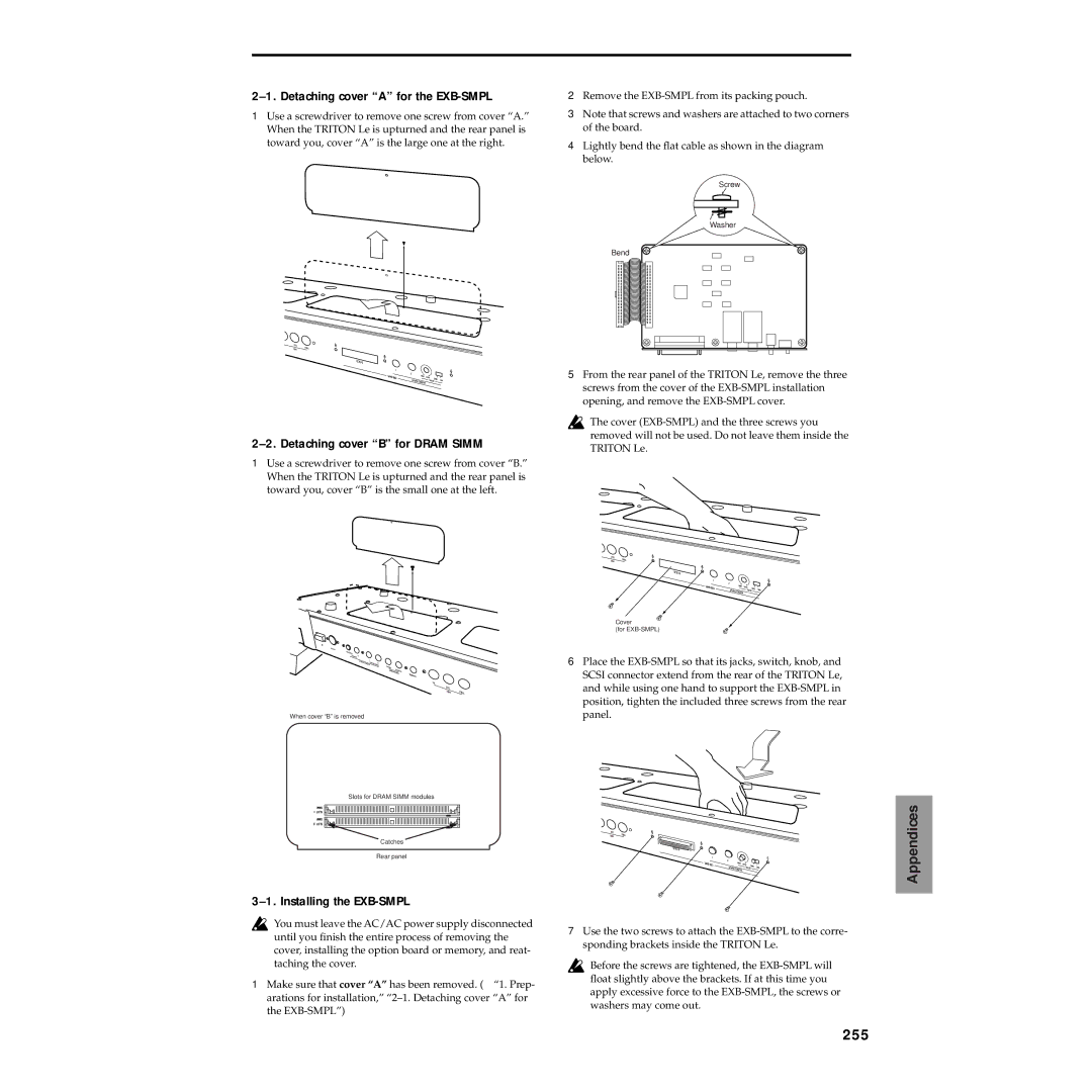
Detaching cover a for the EXB-SMPL
Installing the EXB-SMPL
255
Detaching cover B for Dram Simm
Installing additional Dram SIMM’s
Installing Dram Simm sample data RAM modules
256
Checking after installation
257
Numerics
Index
258
259
Delete
260
Menu
261
262