Administration Guide
Cisco Systems, Inc. All rights reserved OL-17899-02
Basic Administration of the SPA9000
Contents About This Document
Getting Started
Configuring Your System for Itsp Interoperability
Contents
Configuring Phone Lines and Calling Routing Behavior
Configuring Dial Plans
Administering the SPA400 and Voice Mail Service 102
Configuring Music on Hold 125
Appendix a Advanced Topics in SPA9000 Administration 165
Contents Configuring the Auto Attendant 131
Localization 151
Advanced Topics for SPA400 Voice Mail Service 178
Appendix B SPA9000 Field Reference 191
Appendix D Where to Go From Here 275
Appendix C SPA400 Field Reference 261
Contents Appendix E Glossary 278 Appendix F Acronyms 281
Audience
Purpose
Preface
Firmware
Product Firmware Version
Organization
Chapter Description
Document Conventions
Typographic Meaning Element
Boldface
Monospaced
Press Enter
Click Search
SPA9000 Voice System Administration Guide
Getting Started
Introduction to the SPA9000 Voice System
SPA9000 IP PBX
Getting Started
Deployment Scenarios
IP Phones and Accessories
SPA400 SIP-PSTN Gateway and Voicemail Server
Pstn Access and Local Voice Mail
Itsp Service Only
Itsp Service, Pstn Access and Local Voice Mail
Itsp Service, Pstn and Isdn Access and Local Voice Mail
Initial Installation, and Configuration
Basic Administration of the SPA9000
Basic Administration of the SPA9000
Upgrading Firmware for the SPA9000
Basic Administration of the SPA9000
Connecting to the SPA9000 Administration Web Server
Saving or Discarding Changes SPA9000
Access Levels
Setting Passwords for User and Administrator Accounts
Configuring Basic Settings
Click Voice tab System
Click Submit All Changes
Setting the Date and Time
Setting Up the WAN Connection for the SPA9000
Click Router tab Wan Setup
Syntax and Examples
Configuring Daylight Saving Time
Click Submit All Changes Click Voice tab Regional
HHmmss
Entering the Daylight Saving Time Rule
Day
SPA9000 Ethernet Port
Configuring Multicast Addressing and Group Paging
LAN and Application Guidelines
Setting the Multicast Address
Click Voice tab SIP
Setting the Group Page Address
Collecting System Logs and Debug Information
Click Voice tab System
Examples
Click Voice tab Line. Change SIP Debug Option to none
Viewing Information about the SPA9000
Viewing Information about Client Stations
Using the Interactive Voice Response Unit
Using the IVR Menu
IVR Action
IVR Options
Parameters Menu Choice
IVR
IVR
NON-DEFAULT
Entering a Password through the IVR
Basic Administration of the SPA9000
Configuring Your System for Itsp Interoperability
About the SPA9000 Voice System and SIP
Configuring Your System for Itsp Interoperability
SIP Requests and Responses for Internal Calls
Configuring NAT Mapping with a Static IP Address
Network Address Translation NAT and Voice over IP VoIP
NAT Mapping with Session Border Controller
NAT Mapping with SIP-ALG Router
Requirements
Configuring NAT Mapping with Stun
Stun Server Enter the IP address for your Stun server
Click Voice tab System
Firewalls and SIP
Configuring SIP Timer Values
Configuring Phone Lines and Calling Routing Behavior
Configuring SPA9000 FXS Ports
Configuring Phone Lines and Calling Routing Behavior
Configuring Line Interfaces on the SPA9000
Configuring a Line Interface for Itsp Service
SPA9000 Voice Line
Configuring a Line Interface for a SPA400 Pstn or Voice Mail
Register Expires
Page
Configuring Call Capacity for a Line Interface
Bandwidth Requirements and Call Capacity
Bandwidth Budgeting
Setting the Call Capacity Parameter
About Dial Plans
Configuring Dial Plans
Digit Sequences
Digit Sequence Function
Digit Sequence Examples
Example 9
Example
S0 or L0
Local dialing with seven-digit number
Blocked number
Acceptance and Transmission the Dialed Digits
Terminating Event Processing
Syntax for the Dial Plan Timer
Dial Plan Timer Off-Hook Timer
Examples for the Dial Plan Timer
Interdigit Long Timer Incomplete Entry Timer
Syntax for the Interdigit Long Timer
Example for the Interdigit Long Timer
Interdigit Short Timer Complete Entry Timer
Syntax for the Interdigit Short Timer
Examples for the Interdigit Short Timer
Editing Dial Plans
Editing the System Dial Plan
Entering a Phone Dial Plan
814082-9xxxxxx 9,8,12-9xxxxxxxxx 9,8,011xx ,8,xx.1-8xx
Resetting the Control Timers
Entering the Line Interface Dial Plan
Managing the Line Selection for Outbound Calls
Line Availability
Configuring a Call Routing Rule
Other elements
Configuring Phone Lines and Calling Routing Behavior
Entering a Call Routing Rule
Managing Caller ID Settings for Outgoing Calls
Call Forwarding Support on SPA9000
Called Caller Forward Target Remarks Party
Call Transfer Bridge Mode
Call Forward Bridge Mode
Call Transfer Support on SPA9000
Managing Inbound Calls with the Contact List
Routing an Inbound Call to the Auto Attendant
Example Contact List Rules
Example 97255501551009725550156101
Example 2 4085550122500140855501235000,cfwd=aa
Supporting Multiple did Numbers Per Line Interface
Example 530?,hunt=ra102,cfwd=vm25404
Example SIP Header
Supporting Direct Inward Dialing to Phone Extensions
Example Contact List Rule
DID-to-Extension Mapping Example
Syntax
Configuring Phone Lines and Calling Routing Behavior
Entering a Contact List Rule
Managing Inbound Calls with Hunt Groups
Syntax for Hunt Rules
Global Hunt Rule
Line-Specific Hunt Rule
Parameters
Global Rule 500name=Sales,101,102,103,hunt=al
Examples for Hunt Rules
Line-Specific Rule 101,102,103,hunt=al
Line-Specific Rule 1*,hunt=al
Creating a Hunt Rule
Configuring Phone Lines and Calling Routing Behavior
Managing Inbound Calls with Shared Line Appearances
About Shared Line Appearances
Share Ext Choose shared
SPA9xx Telephone Configuration Ext Subscriber Information
If needed, configure additional line keys for the same SLA
Administering the SPA400 and Voice Mail Service
Connecting to the SPA400 Administration Web Server
Administering the SPA400 and Voice Mail Service
Configuring the SPA400 Network Connection
Click Setup tab Basic Setup
Saving or Discarding Changes on the SPA400
Domain Name Server DNS Address section
Click Administration tab Management
Gateway Password Type the password
Click Save Settings
Click Administration tab Reboot
Click Administration tab Firmware Upgrade
Upgrading the Firmware for the SPA400
Configuring a SPA400 to Interoperate with the SPA9000
Call Signalling Packets RTP Packets b8
Click Setup tab SPA9000 Interface
User ID
Click Setup tab Voice
Preferred Codec Select G.711u
Configuring a SPA400 for Pstn Access
Configuring a SPA400 for Voice Mail Service
Voice Mail Capacity
Configuring Local Voice Mail Service on a SPA400
Click Setup tab Voicemail Server
Server Port
SPA9000 subscriber ID
Mailbox manage number
Mailbox deposit number
Click the Voicemail Users tab
SPA400 Status
Setting Up Voice Mail on Each Station
Scroll down to Call Feature Settings
SPA400 Setup Voicemail Users
Enabling Remote Voice Mail Access Optional
Syntax 10xxxx.dialcodevmmN
Click Administration tab USB Setting
Managing the Voice Mail Messages on the USB Key
Enabling Debugging on the SPA400
Click Event Logs tab
Click Save Settings Click Setup tab Basic Setup
SPA400 Setup Basic Setup
Using the Internal Music Source for Music On Hold
Using the Internal Music Source
Configuring Music on Hold
Changing the Music File for the Internal Music Source
Configuring a Streaming Audio Server
About the Streaming Audio Server
SPA9000 Voice System Administration Guide 128
Configuring the Streaming Audio Server
Using the IVR with an SAS Line
Configuring the Auto Attendant
How the Auto Attendant Works
Configuring the Auto Attendant
Default AA Prompts Prompt ID Default Audio Content
Using Pre-Recorded Prompts
Working with the Auto Attendant Greetings
Recording an Auto Attendant Prompt
Example Prompts
Example AA Prompts Prompt ID Message
Using the IVR Prompts to Change Recordings
IVR Prompt Menu Call Flow
Downloading Prompts
Example
Elements of the Default AA Script
Writing an Auto Attendant Script
Noinput timeout=10
Default
Target=$input Default Match Form
Audio src=prompt1
Elements of an AA Script with a Sub-Menu
Example 2 Routing Calls with a Departmental Sub-Menu
Form id=DIR type=menu
Case input=1
Goto next=SALES
Case
Target=$input
Elements of XML Scripting Grammar
Audio Instruction
Action Instruction
Noinput Instruction
Example goto link= dirdlg
Example xfer name= Technical Support target=
Nomatch Instruction
Menu Matched Instruction for Touch Tone Dmtp Input
Auto Attendant XML Instructions Set
AA XML Elements Instruction Description Syntax and Examples
Performs the default case
Instruction Description Syntax and Examples
Entering an Auto Attendant Script
Syntax start=hhmmssend=hhmmss Example start=083000end=180000
SPA9000 Voice System Administration Guide 149
Example 1, Default AA Dial Plan 1
Configuring Dial Plans for the Auto Attendant
Example 2 x500x408555xxxxxxxxx
Localization
Localizing the SPA9000 Auto Attendant Prompts
Localization
Click Voice tab the SIP tab
SPA9000 Voice System Administration Guide 153
Configuring the SPA9000 and SPA9xx Call Progress Tones
Local Time Configuration
SPA9000 Daylight Saving Time Rules
SPA9000 Call Progress Tones by Country Australia Dial Tone
Outside Dial Tone
Prompt Tone
Reorder Tone
Germany Dial Tone
France Dial Tone
Ireland Dial Tone Outside Dial Tone
Italy Dial Tone
Netherlands Dial Tone
Portugal Dial Tone
Norway Dial Tone
Spain Dial Tone
Sweden Dial Tone
Localizing the SPA400 Voice Mail Prompts
Localizing the SPA400 Call Disconnect Tones
SPA400 Call Processing Tones
Processing Tones
Click Administration Reboot
Localizing the SPA400 Caller ID Method
To restart the SPA400, complete the following tasks
Advanced Topics in SPA9000 Administration
Technology Background
Advanced Topics in SPA9000 Administration
Session Initiation Protocol
SPA9000 Media Proxy
SPA9000 as a SIP Proxy
Using the SPA9000 with a Firewall or Router
SPA400 SIP-PSTN Gateway
SPA400 as a SIP-PSTN Gateway
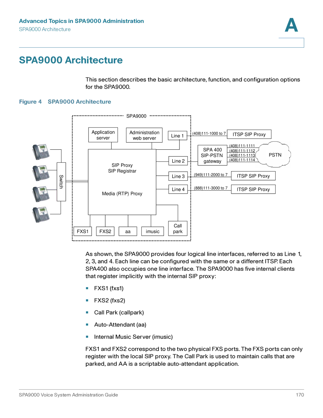
SPA9000 Architecture
SPA9000 Architecture
Architectural Component Function
SIP-NAT Interoperation
Configuring Vertical Supplementary Service Codes
Advanced Call Control and Routing
SPA9000 Voice System Administration Guide 174
Managing the Outbound Call Routing Groups
Call Routing Group Membership
Group 1 User ID 11?
Group 2 User ID 101, 102
Configuring an Outbound Call Routing Group
Call Routing Group Line Preference
Group 1 Line 2,1
Group 2 Line 3,1
Configuring Outbound Call Codec Selection Codes
Advanced Topics for SPA400 Voice Mail Service
How Voicemail Works
Checking Voicemail from an External Number
Depositing Voicemail
18005551000vmm3
7vmm4
SPA9000 Voice System Administration Guide 181
Subscribing to Voicemail Notification
Using Configuration Profiles
Remote Provisioning Features
AdminPasswd some secret UpgradeEnable Yes
Client Auto-Configuration
Manual Client Configuration
Dhcp
SPA9000 Voice System Administration Guide 186
Variables Used in XML Configuration Files Description
Client Registration
Using the Upgrade URL
Using the Reboot URL
Using the Resync URL
Admin/upgrade?tftp//192.168.2.251/spa.bin
Router Tab
Status
System Status section
Product Information section
SPA9000 Field Reference
Wan Setup
Internet Connection Settings section
Static IP Settings section
PPPoE Settings section
Optional Settings section
Default
MAC Clone Settings section
Remote Management section
QOS Settings section
Lan Setup page and Application
Vlan Settings section
Voice tab
Info
FXS 1/2 Status section
Line 1/2/3/4 Status section
Auto Attendant Prompt Status section
System
Internal Music Status section
System Configuration section
Miscellaneous Settings section
SIP
SIP Parameters section
Default application/dtmf-relay
Default application/hook-flash
SIP Timer Values sec section
SIP T2
SPA9000 Voice System Administration Guide 205
Response Status Code Handling section
SIT1 RSC
RTP Parameters section
SDP Payload Types section
Default telephone-event
NAT Support Parameters section
EXT IP
PBX Parameters section
SPA9000 Voice System Administration Guide 213
Default L1,2,3,49xx
Rule = Ln,n,n,npattern
Example 1,3
Internal Music Source Parameters section
Section = nstart/end/pausepause2
AA script. See , Configuring the Auto Attendant
Auto Attendant Parameters section
SPA9000 Voice System Administration Guide 219
SPA9000 Voice System Administration Guide 220
SPA9000 Voice System Administration Guide 221
PBX Phone Parameters section
Xx3469110002-9xxxxxx1xxx2
9xxxxxxS0xxxxxxxxxxxx
Xxxxxxxxxxxx. Allows any entry of 12 or more digits
Do not include flat-profile…/flat-profile. The SPA9000
Default 350@-19,440@-1910*/0/1+2
Provisioning
Regional
Call Progress Tones section
Default 420@-19,520@-1910*/0/1+2
Default 420@-1610*/0/1
Default 520@-19,620@-1910*/0/1+2
Default 480@-19,620@-1910.5/.5/1+2
Distinctive Ring Patterns section
Distinctive Call Waiting Tone Patterns section
Distinctive Ring/CWT Pattern Names section
Control Timer Values sec section
Ring and Call Waiting Tone Spec section
SPA9000 Voice System Administration Guide 230
Vertical Service Activation Codes section
SPA9000 Voice System Administration Guide 232
SPA9000 Voice System Administration Guide 233
SPA9000 Voice System Administration Guide 234
SPA9000 Voice System Administration Guide 235
Vertical Service Announcement Codes section
Outbound Call Codec Selection Codes section
Miscellaneous section
Syntax start = start-time end=end
Time save = save-time
600, 900, 600+2.16uF, 900+2.16uF, 270+750150nF
220+850120nF, 220+820115nF, or 200+600100nF
7end=10/-1/7save=1
Default BellcoreN.Amer, China
202 or
Line Enable section
FXS 1/2
Network Settings section
SIP Settings section
Disable
Default up and down
Register
Subscriber Information section
Dial Plan section
Mailbox Status section
Streaming Audio Server SAS section
Call Feature Settings section
Audio Configuration section
For example, conf@myserver.com12345 or conf
Default Unspecified
SPA9000 Voice System Administration Guide 249
Default caller or callee
Line 1/2/3/4
FXS Port Polarity Configuration section
Reverse
Voice tab Line
SIP Guid
SPA9000 Voice System Administration Guide 254
SPA9000 Voice System Administration Guide 255
NAT Settings section
Proxy and Registration section
Mbs = mbidnew/old
SPA9000 Voice System Administration Guide 259
SPA9000 Voice System Administration Guide 260
Setup
SPA400 Field Reference
Basic Setup
SPA9000 Interface
SPA 9000 Address
Signaling
Port ID
Voice
Voice Codecs
Calling Timers
Voice Setting
Dialing Parameters
Line Settings
Default Less than 0.5ms
Default 13.5-16.5vrms
Default North American
Voicemail Settings
Voicemail Server
8888@192.168.0.1105090
Mailbox Deposit URL 900@192.168.0.1105090
Voicemail Users
User Setting
Mailbox Manage URL 800@192.168.0.1105090
Administration
Factory Default
Local Access
Management
Firmware Upgrade
USB Setting
Reboot
Status
Gateway
Gateway Information
Internet Connection
Event Logs
Set Log Level
FXO Line status
Event Log Level
Call process tone configuration
Call process tone Detection Tone Setting
Tone
Repeat
Product Resources
Resource Location
Related Documentation
Where to Go From Here
Document Title Description Intended Audience
SPA9000 Voice System
Glossary
Glossary
SPA9000 Voice System Administration Guide 280
Acronyms
Acronyms
Mgcp
SLA