1−10
Getting started
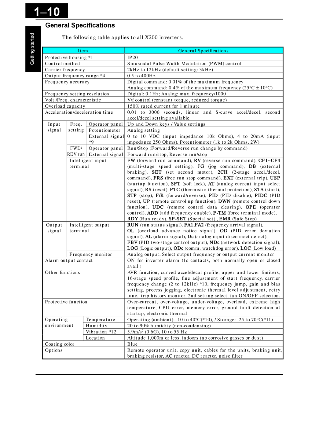
General Specifications
The following table applies to all X200 inverters.
|
| Item | General Specifications | ||
| Protective housing *1 | IP20 | |||
| Control method |
| Sinusoidal Pulse Width Modulation (PWM) control | ||
| Carrier frequency |
| 2kHz to 12kHz (default setting: 3kHz) | ||
| Output frequency range *4 | 0.5 to 400Hz | |||
| Frequency accuracy | Digital command: 0.01% of the maximum frequency | |||
|
|
|
|
| Analog command: 0.4% of the maximum frequency (25°C ± 10°C) |
| Frequency setting resolution | Digital: 0.1Hz; Analog: max. frequency/1000 | |||
| Volt./Freq. characteristic | V/f control (constant torque, reduced torque) | |||
| Overload capacity |
| 150% rated current for 1 minute | ||
| Acceleration/deceleration time | 0.01 to 3000 seconds, linear and | |||
|
|
|
|
| accel/decel setting available |
| Input | Freq. | Operator panel | Up and Down keys / Value settings | |
| signal | setting | Potentiometer | Analog setting | |
|
|
|
| External signal | 0 to 10 VDC (input impedance 10k Ohms), 4 to 20mA (input |
|
|
|
| *9 | impedance 250 Ohms), Potentiometer (1k to 2k Ohms, 2W) |
|
| FWD/ | Operator panel | Run/Stop (Forward/Reverse run change by command) | |
|
| REV run | External signal | Forward run/stop, Reverse run/stop | |
|
| Intelligent input | FW (forward run command), RV (reverse run command), CF1~CF4 | ||
|
| terminal | |||
|
|
|
|
| braking), SET (set second motor), 2CH |
|
|
|
|
| command), FRS (free run stop command), EXT (external trip), USP |
|
|
|
|
| (startup function), SFT (soft lock), AT (analog current input select |
|
|
|
|
| signal), RS (reset), PTC (thermistor thermal protection), STA (start), |
|
|
|
|
| STP (stop), F/R (forward/reverse), PID (PID disable), PIDC (PID |
|
|
|
|
| reset), UP (remote control up function), DWN (remote control down |
|
|
|
|
| function), UDC (remote control data clearing), OPE (operator |
|
|
|
|
| control), ADD (add frequency enable), |
|
|
|
|
| RDY (Run ready), |
| Output | Intelligent output | RUN (run status signal), FA1,FA2 (frequency arrival signal), | ||
| signal | terminal | OL (overload advance notice signal), OD (PID error deviation | ||
|
|
|
|
| signal), AL (alarm signal), Dc (analog input disconnect detect), |
|
|
|
|
| FBV (PID |
|
|
|
|
| LOG (Logic output), ODc (comm. watchdog error), LOC (Low load) |
|
| Frequency monitor | Analog output; Select output frequency or output current monitor | ||
| Alarm output contact | ON for inverter alarm (1c contacts, both normally open or closed | |||
|
|
|
|
| avail.) |
| Other functions |
| AVR function, curved accel/decal profile, upper and lower limiters, | ||
|
|
|
|
| |
|
|
|
|
| frequency change (2 to 12kHz) *10, frequency jump, gain and bias |
|
|
|
|
| setting, process jogging, electronic thermal level adjustment, retry |
|
|
|
|
| func., trip history monitor, 2nd setting select, fan ON/OFF selection. |
| Protective function | ||||
|
|
|
|
| temperature, CPU error, memory error, ground fault detection at |
|
|
|
|
| startup, electronic thermal |
| Operating |
| Temperature | Operating (ambient): | |
| environment |
| Humidity | 20 to 90% humidity | |
|
|
|
| Vibration *12 | 5.9m/s2 (0.6G), 10 to 55 Hz |
|
|
|
| Location | Altitude 1,000m or less, indoors (no corrosive gasses or dust) |
| Coating color |
| Blue | ||
| Options |
|
|
| Remote operator unit, copy unit, cables for the units, braking unit, |
|
|
|
|
| braking resistor, AC reactor, DC reactor, noise filter |
|
|
|
|
|
|