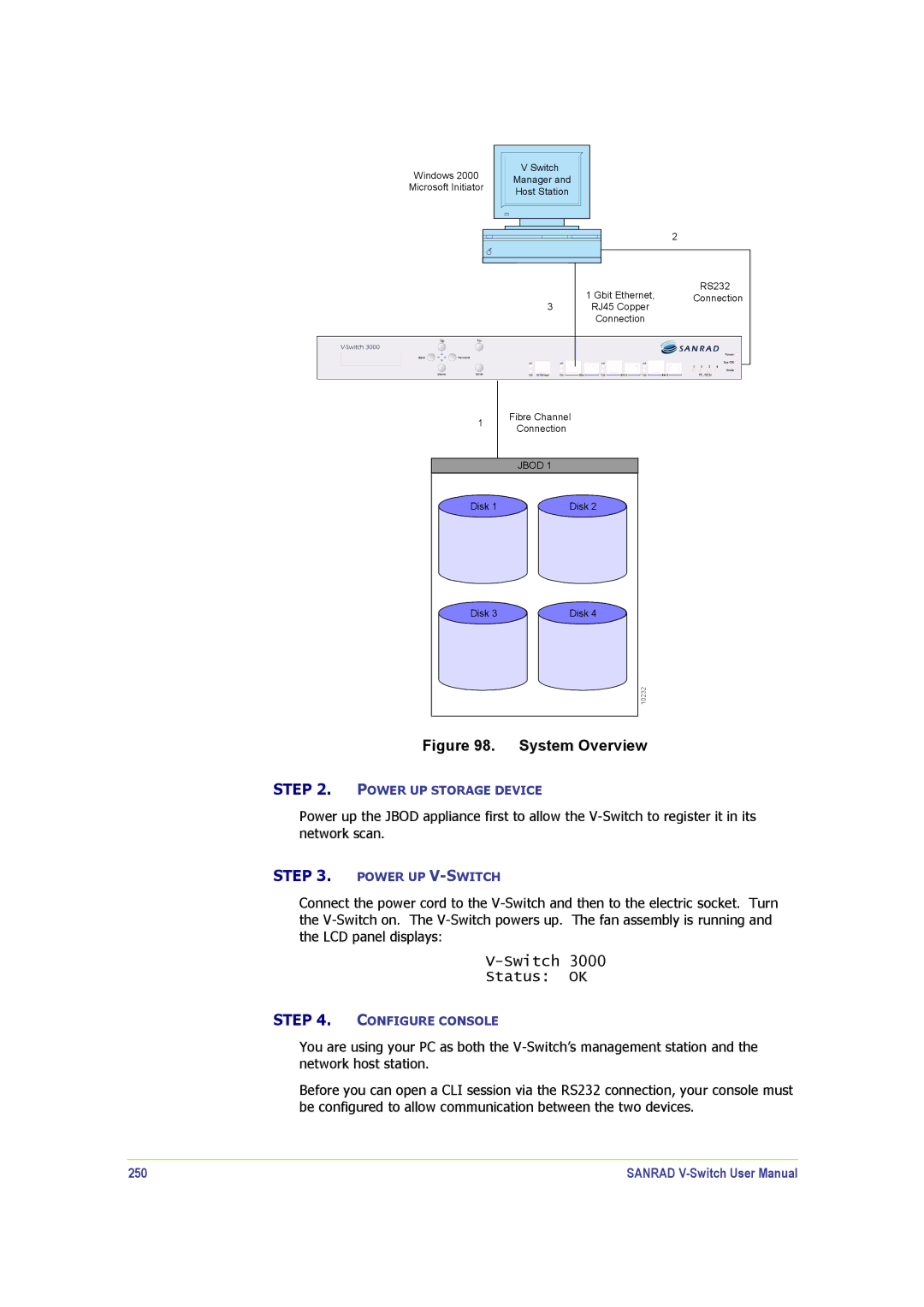
Windows 2000
Microsoft Initiator
V Switch |
Manager and |
Host Station |
2
3
RS232
1 Gbit Ethernet, Connection
RJ45 Copper
Connection
1 | Fibre Channel | |
Connection | ||
| ||
| JBOD 1 | |
Disk 1 | Disk 2 | |
Disk 3 | Disk 4 | |
| 10232 |
Figure 98. System Overview
STEP 2. POWER UP STORAGE DEVICE
Power up the JBOD appliance first to allow the
STEP 3. POWER UP
Connect the power cord to the
V-Switch 3000
Status: OK
STEP 4. CONFIGURE CONSOLE
You are using your PC as both the
Before you can open a CLI session via the RS232 connection, your console must be configured to allow communication between the two devices.
250 | SANRAD |