Telnet |
Station |
| Initiator Target: | |||
| 212.199.43.56 | |||
IP address: |
|
|
| Initiator Targets: |
212.199.43.75 | ||||
212.199.43.40 |
|
| 212.199.43.56 | |
| ||||
|
| Host 1 |
|
|
|
| IP address: |
| |
| 212.199.43.50 | |||
| Host 2 |
| IP address: |
| 212.199.43.70 |
| LAN B |
2 | 2 |
Eth 1: 212.199.43.41 |
|
Eth 1: 212.199.43.56
10235
V Switch 1 |
| V Switch 2 | |
| Fibre Channel | Eth 1: 212.199.43.42 | |
| Eth 1: 212.199.43.75 | ||
| Connection | ||
1 | 1 | ||
|
JBOD 1
Disk 1 | Disk 2 |
Disk 3 | Disk 4 |
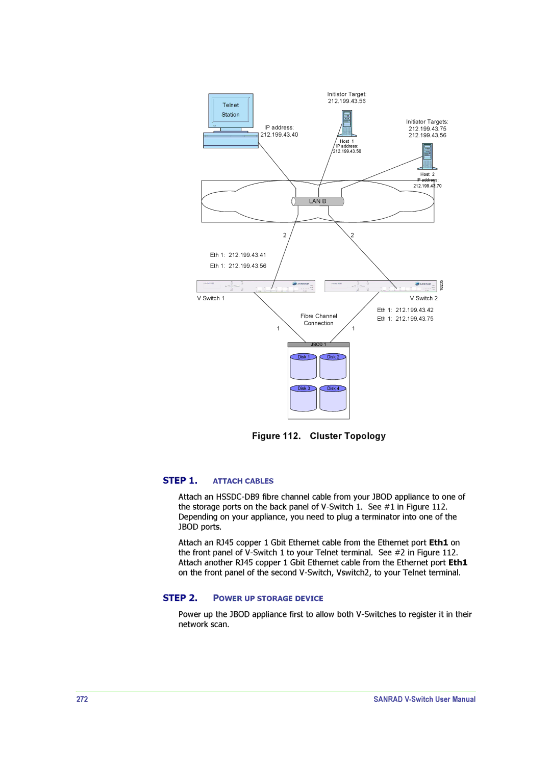
Figure 112. Cluster Topology
STEP 1. ATTACH CABLES
Attach an
Attach an RJ45 copper 1 Gbit Ethernet cable from the Ethernet port Eth1 on the front panel of
STEP 2. POWER UP STORAGE DEVICE
Power up the JBOD appliance first to allow both
272 | SANRAD |