SANRAD V-Switch manual Switch Cluster Configuration

Models: V-Switch

1 300
Download 300 pages 15.92 Kb
Page 79
Image 79

.

Vol 1

iSCSI

iSCSI

Vol 2


initiator

initiator


IP1,Target 1

Host 1

Host 2

IP2,Target 2

Cloud

IP SAN

IP1-active

IP2-active

IP2-inactive

IP1-inactive

When creating a cluster, it is recommended that the same port on each V-Switch is used to connect to the same FC storage device. This increases the chance of the storage device receiving the same

V Switch 1

iSCSI Target 1

wwui1

Vol 1

LU0

V Switch 2

iSCSI Target 2

wwui2

Vol 2

LU0

default storage number on both V- Switches during their auto-discovery cycles. This, in turn, makes cluster configuration easier.


JBOD

Disk 1

Disk 2

Disk 3

Disk 4


10267

When working in a cluster, the V-Switch can support a maximum of 100 portals: 50 active and 50 inactive.

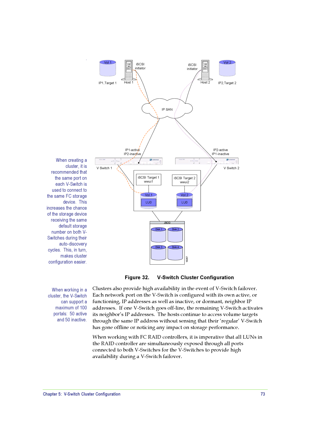
Figure 32. V-Switch Cluster Configuration

Clusters also provide high availability in the event of V-Switch failover. Each network port on the V-Switch is configured with its own active, or functioning, IP addresses as well as inactive, or dormant, neighbor IP addresses. If one V-Switch goes off-line, the remaining V-Switch activates its neighbor’s IP addresses. The hosts continue to access volume targets through the same IP address without sensing that their ‘regular’ V-Switch has gone offline or noticing any impact on storage performance.

When working with FC RAID controllers, it is imperative that all LUNs in the RAID controller are simultaneously exposed through all ports connected to both V-Switches for the V-Switches to provide high availability during a V-Switch failover.

Chapter 5: V-Switch Cluster Configuration

73

Page 79
Image 79
SANRAD V-Switch manual Switch Cluster Configuration