Appendix A Voice Cards and PIMG Units
Intel Dialogic D/41EPCI,
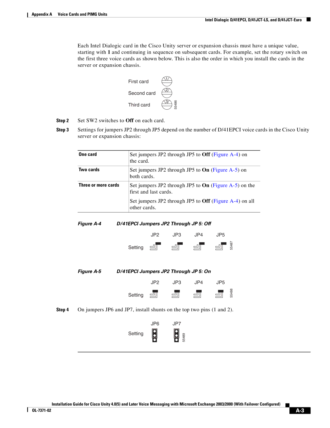
Each Intel Dialogic card in the Cisco Unity server or expansion chassis must have a unique value, starting with 1 and continuing in sequence on subsequent cards. For example, set the rotary switch on the first three voice cards as shown below. This is also the order in which you install the cards in the server or expansion chassis.
|
| 1 |
|
|
|
| First card |
|
|
|
| 2 |
|
|
|
| Second card |
|
|
|
| 3 | 55486 |
|
|
| Third card |
| |
|
|
|
| |
Step 2 | Set SW2 switches to Off on each card. |
|
| |
Step 3 | Settings for jumpers JP2 through JP5 depend on the number of D/41EPCI voice cards in the Cisco Unity | |||
| server or expansion chassis: |
|
| |
|
|
|
| |
| One card | Set jumpers JP2 through JP5 to Off (Figure | ||
|
| the card. |
|
|
|
|
|
| |
| Two cards | Set jumpers JP2 through JP5 to On (Figure | ||
|
| both cards. |
|
|
|
|
|
| |
| Three or more cards | Set jumpers JP2 through JP5 to On (Figure | ||
|
| first and last cards. |
|
|
Set jumpers JP2 through JP5 to Off (Figure
Figure A-4 D/41EPCI Jumpers JP2 Through JP 5: Off
JP2 JP3 JP4 JP5
Setting
55487
Figure A-5 D/41EPCI Jumpers JP2 Through JP 5: On
JP2 JP3 JP4 JP5
Setting
55488
Step 4 On jumpers JP6 and JP7, install shunts on the top two pins (1 and 2).
Setting
JP6 JP7
55489
Installation Guide for Cisco Unity 4.0(5) and Later Voice Messaging with Microsoft Exchange 2003/2000 (With Failover Configured)
|
| |
|