Chapter 3 Setting Up the Hardware
Installing Voice Cards
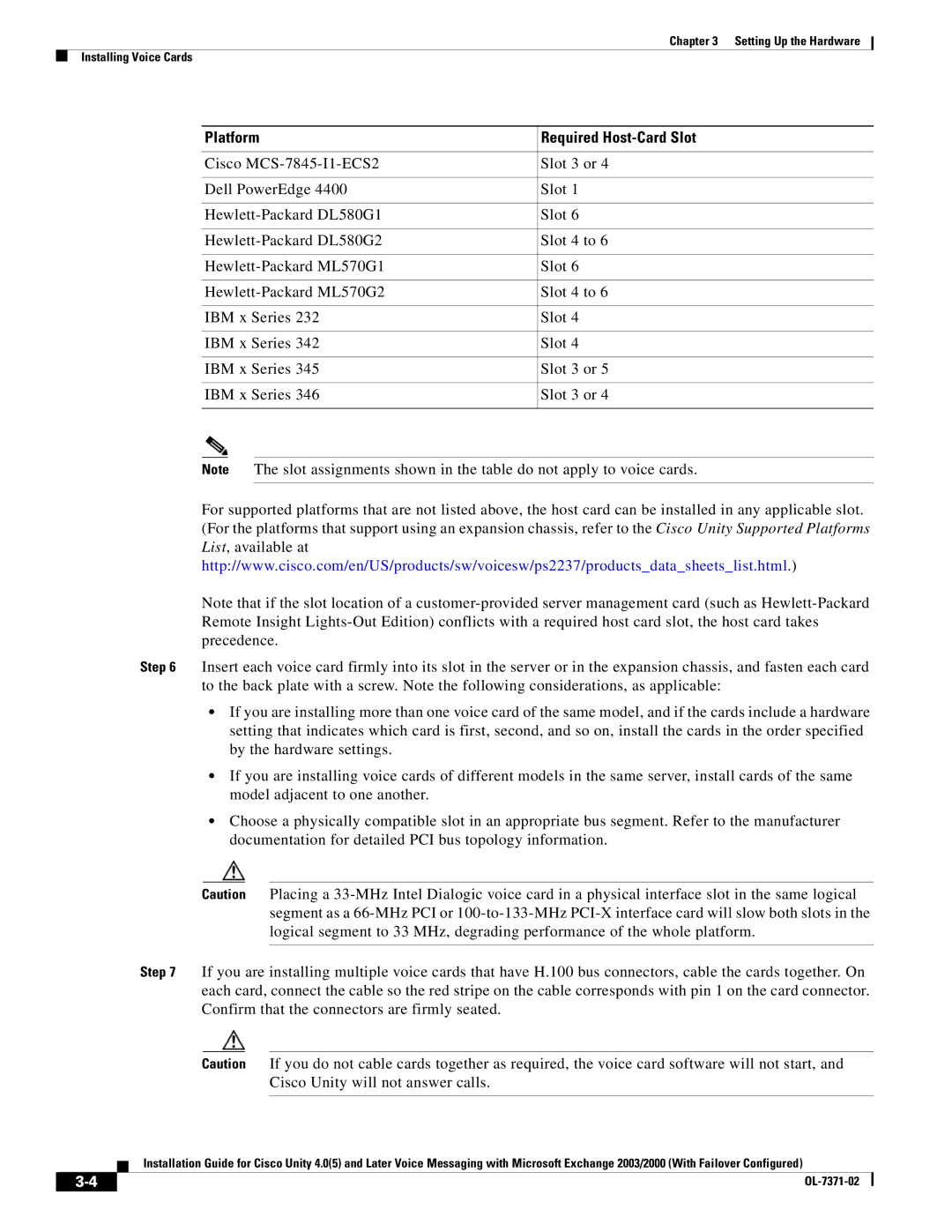
Platform | Required |
|
|
Cisco | Slot 3 or 4 |
|
|
Dell PowerEdge 4400 | Slot 1 |
|
|
Slot 6 | |
|
|
Slot 4 to 6 | |
|
|
Slot 6 | |
|
|
Slot 4 to 6 | |
|
|
IBM x Series 232 | Slot 4 |
|
|
IBM x Series 342 | Slot 4 |
|
|
IBM x Series 345 | Slot 3 or 5 |
|
|
IBM x Series 346 | Slot 3 or 4 |
|
|
Note The slot assignments shown in the table do not apply to voice cards.
For supported platforms that are not listed above, the host card can be installed in any applicable slot. (For the platforms that support using an expansion chassis, refer to the Cisco Unity Supported Platforms List, available at http://www.cisco.com/en/US/products/sw/voicesw/ps2237/products_data_sheets_list.html.)
Note that if the slot location of a
Step 6 Insert each voice card firmly into its slot in the server or in the expansion chassis, and fasten each card to the back plate with a screw. Note the following considerations, as applicable:
•If you are installing more than one voice card of the same model, and if the cards include a hardware setting that indicates which card is first, second, and so on, install the cards in the order specified by the hardware settings.
•If you are installing voice cards of different models in the same server, install cards of the same model adjacent to one another.
•Choose a physically compatible slot in an appropriate bus segment. Refer to the manufacturer documentation for detailed PCI bus topology information.
Caution Placing a
Step 7 If you are installing multiple voice cards that have H.100 bus connectors, cable the cards together. On each card, connect the cable so the red stripe on the cable corresponds with pin 1 on the card connector. Confirm that the connectors are firmly seated.
Caution If you do not cable cards together as required, the voice card software will not start, and Cisco Unity will not answer calls.
Installation Guide for Cisco Unity 4.0(5) and Later Voice Messaging with Microsoft Exchange 2003/2000 (With Failover Configured)
| ||
|
