Appendix A Voice Cards and PIMG Units
Intel Dialogic
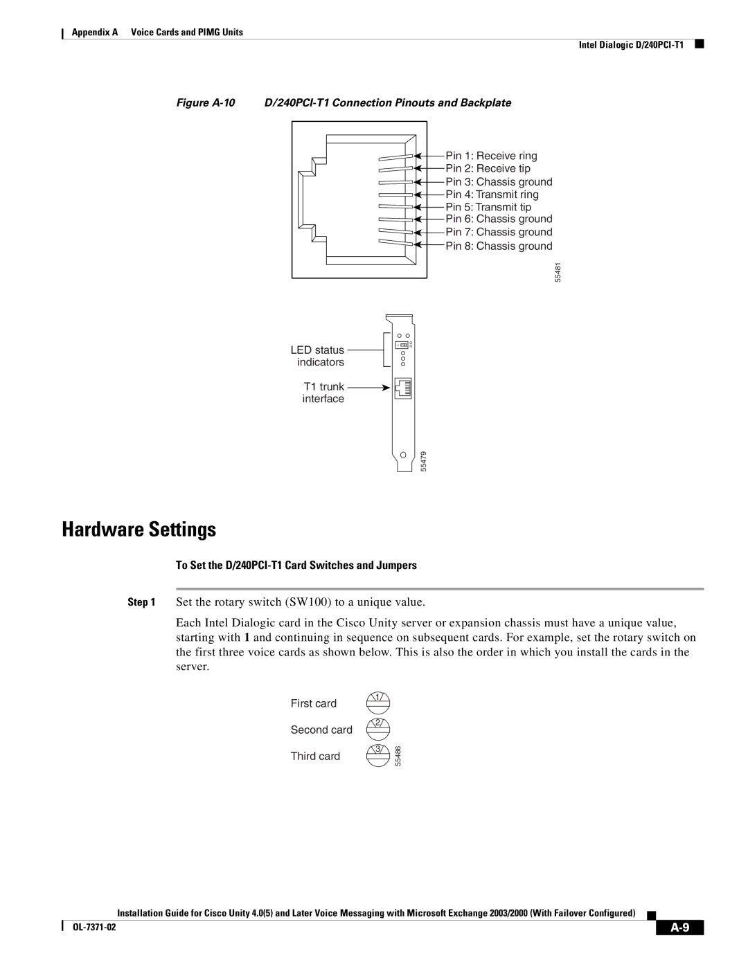
Figure A-10 D/240PCI-T1 Connection Pinouts and Backplate
Pin 1: Receive ring |
Pin 2: Receive tip |
Pin 3: Chassis ground |
Pin 4: Transmit ring |
Pin 5: Transmit tip |
Pin 6: Chassis ground |
Pin 7: Chassis ground |
Pin 8: Chassis ground |
55481 |
LED status indicators
1![]()
![]()
![]()
O N
T1 trunk ![]()
![]()
![]()
![]() interface
interface![]()
55479
Hardware Settings
To Set the D/240PCI-T1 Card Switches and Jumpers
Step 1 Set the rotary switch (SW100) to a unique value.
Each Intel Dialogic card in the Cisco Unity server or expansion chassis must have a unique value, starting with 1 and continuing in sequence on subsequent cards. For example, set the rotary switch on the first three voice cards as shown below. This is also the order in which you install the cards in the server.
First card
1
2
Second card
3
Third card
55486
Installation Guide for Cisco Unity 4.0(5) and Later Voice Messaging with Microsoft Exchange 2003/2000 (With Failover Configured)
|
| |
|